


Maudesmaster
-
Posts
79 -
Joined
-
Last visited
Content Type
Profiles
Forums
Events
Gallery
Blogs
Store
Posts posted by Maudesmaster
-
-
Hi i need recommendations for new prop size I have a 62’ narrow boat with a Gardner 3LW and PRM 500 2:1 reduction gear box and 24” between Skeg and uxter
I have a 21” 18 pitch propeller which is very slow on the forward uptake and full revs only gives me walking speed ( little legs wife on tow path ) in locks I have to use full revs to stop boat hitting gates
I am going to order a new prop rather than having existing prop reworked
-
Thank you all drilled and stainless roll pin 6mm X 36mm same as nut AF
-
 1
1
-
-
I have a bronze 19” prop on a narrow boat stainless steel shaft from 3LW
That came with Brass nut and brass washer
How do you all lock the nut
I am thinking of changing nut only to a Stainless steel Nyloc nut any reason as to why not
thank you
-
15 hours ago, dmr said:
This is reviving an old thread 😀.
The force from any small impact, such as nudging the front button against a lock gate, is big, and will likely snap cable ties. I had no success at all with them. Putting a weak link in the chain appears to be the only way to go. This is done by cutting right through a link, probably at the weld. The link then opens up under a dangerous load. This works.
The link will likely open up progressively under normal boating impacts so will need forcing back into shape every few months. I use a small portable vice to do this. Cutting part way through a link or shackle did not work for me.
...............Dave
Wasn’t going to use ty wraps just saying about a bag I bought from toolstation and the cure for them snapping
-
On 14/08/2016 at 14:55, dmr said:
Interesting stuff here, thanks. So now I need to estimate the static load on the tie when the boat adopts a unhealthy angle, this should be within my engineering capabilities, or skill set as people like to say these days.
Interestingly I did some experiments using paracord as the weak link (550 lbs load) and it did break on several occasions when we nudged the gates a little harder than intended. We hang the button just below the nose rather than on the nose otherwise we are too long for a few locks, so a bump at the front can maybe give a bigger tensile force component along the chain. So maybe finding the balance between the boat getting hung up and general shock loads is not trivial
.............Dave
Thank you for this bought a bag of ties from toolstation and they were snapping off before fully tightened I will try the boiling method as desperate and used a few or would have returned them
-
I do have 2 120 amp alternators running off 70mm pulleys to a 14” crank pulley 1 of which I may change to a lesser one for starter batteries It’s a big learning curve however I would never take on a total fit out again 10 hour days and sleepless nights
thank you all for your input will let you know how it’s all gone in September when hoping to launch Maud of the marshes
-
Thank you for all replies feeling a bit sad now
I do have the bowman header tank on the cooling system which was all a bit of a mish mash as as the engine came from a fishing boat
I had to buy a new thermostat housing and re route the pipe work so if all goes t!ts up I can re route through the heat exchanger on the bowman header tank, what would have been great if bowman made them for the Gardner would have been a manifold heat exchanger perhaps
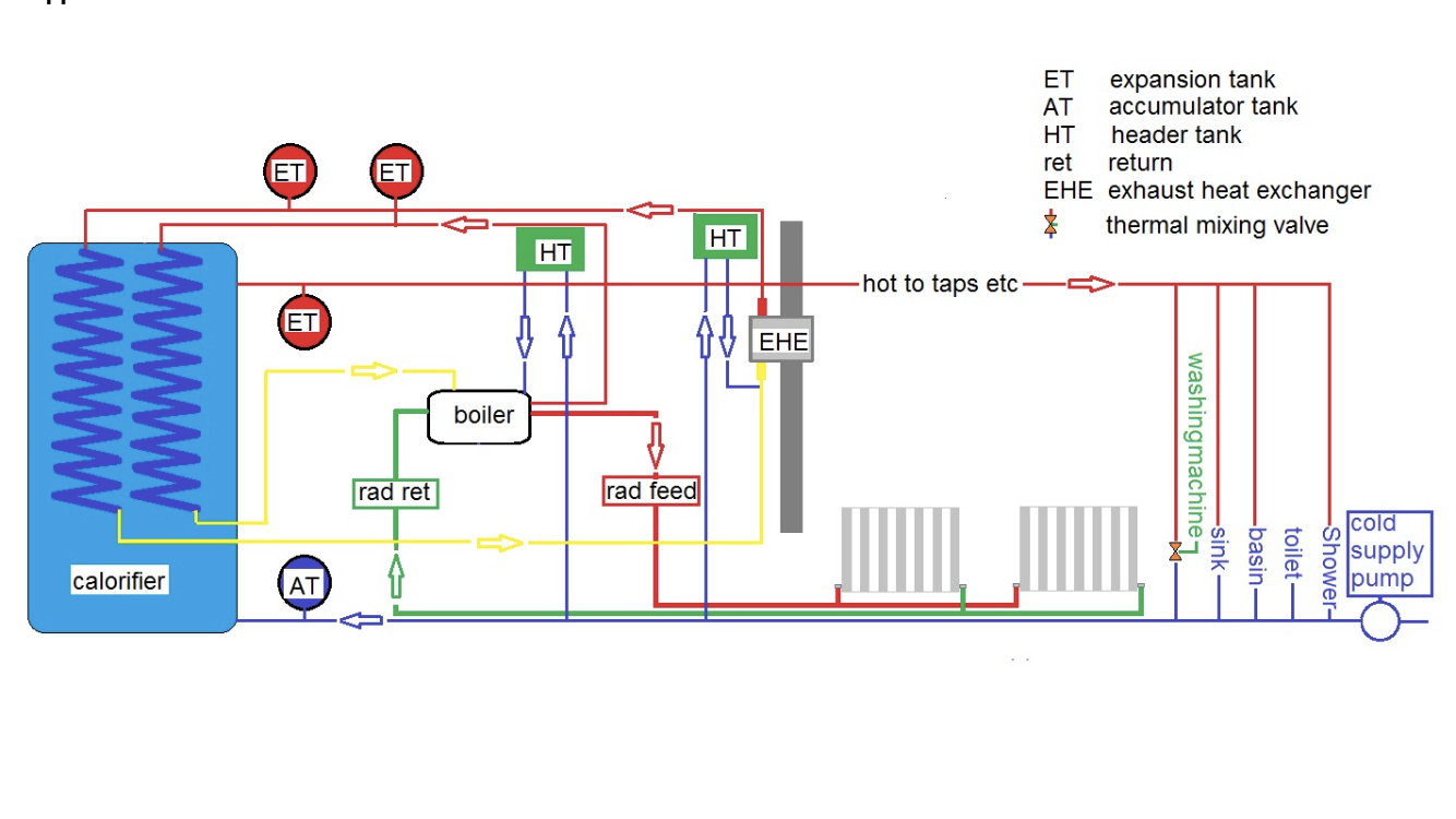
16 hours ago, jonesthenuke said:Interesting. Looks well made.
It seems complicated? I assume your expansion tanks are accumulators. I do not think they are necessary in the hot feed from the boiler and the heat exchanger to the clarifier coils, the expansion duty should be accomplished by the header tank.
Your boiler circuit and your exhaust heat recovery circuit will presumably have pumps?
Are you sure you can recover enough energy from the exhaust to heat the rads as well as the clarifier? Our 3LW exhaust does not get very hot at causing speeds. Also if that is just a plain can wrapped around the exhaust pipe the heat exchange area looks very low, especially given the relatively high exhaust gas flow velocity.
Conversely you need to avoid letting the exhaust get too cool, you do not want the exhaust gases condensing and either being retained in the exhaust or blowing out of the top of the exhaust (think wet black soot, but also somewhat acidic depending on fuel sulphur content)
I have toyed with the idea of recovering heat from our engine but would use a heat exchanger in the cooling system pipework to the skin tank, that is where most of the heat discharge from the engine is going and currently its all thrown away. This approach is a lot simpler, no second head tank, single calorifier coil needed, no second pump etc.
2 hours ago, David Mack said:You were presumably running the engine without any load, so its not really surprising the cooling water did not get hot. You need a thermostat fitted and for the engine to be doing some work to generate a resonable amount of heat.
3 hours ago, steamraiser2 said:I would have thought that a 3LW would not produce enough heat to make this run efficiently. I think that Jones the Nuke is on the right track when mentioning the condensation and black soot which is sure to follow. We always fit a decent thermostat system to the engines (dozens and dozens over the years). This enables the engine to run at the optimum temperature which narrowboat engines seldom do and, once warmed up to supply hot water to one of the calorifier coils. This always works well. The heat loss through the calorifier system is usually significant with the result that the engine stat seldom fully opens and it is unusual for cooling water to circulate through the skin tank except when thrashing up a river etc.
The other thing to bear in mind is the need to prevent circulation through the engine related part of the circuit when the engine is off. Engines make splendid heat sinks and will cool the water in the calorifier overnight.
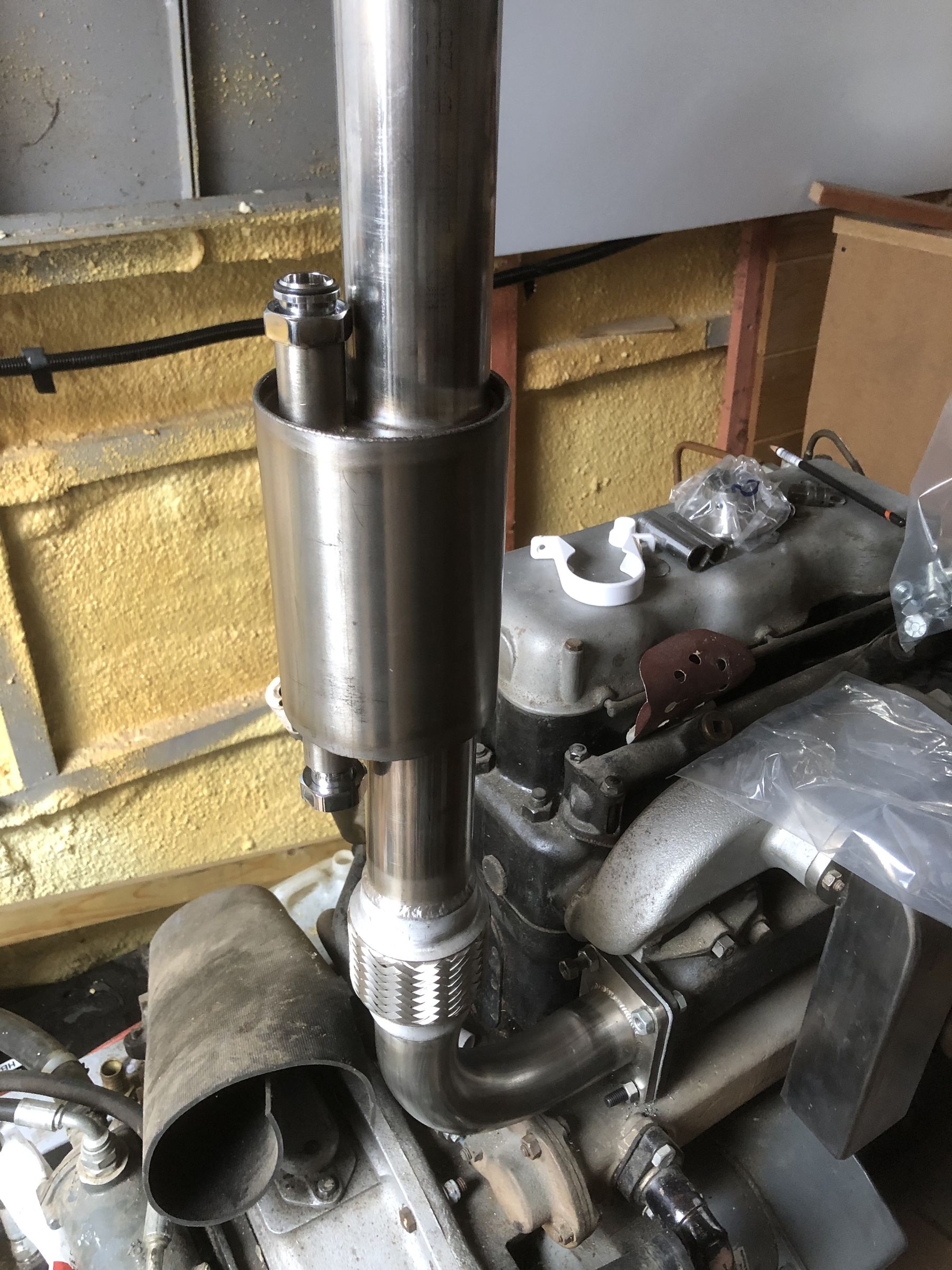
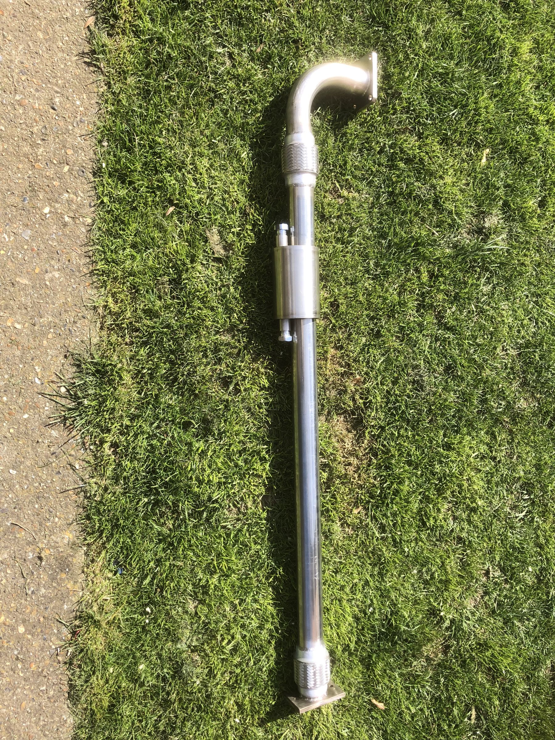
4 hours ago, Maudesmaster said:Thank you for replies
The boat has not been floated as yet, when I first installed and ran the engine with skin tanks full the pipe work to and from skin tanks after 1 hour running the was only luke warm whereas the exhaust was very hot
My thinking was to try this idea out using only a small can with the flanges welded around the exhaust so water did not boil or cool the exhaust gasses too much I can modify the exhaust at a later date
Can I tee into the pipe work so that when engine is running it heats the radiators
-
On 13/02/2019 at 12:17, Boater Sam said:
No reason why not as far as I can see. But then today I have been accused of talking rubbish.
11 hours ago, jonesthenuke said:Interesting. Looks well made.
It seems complicated? I assume your expansion tanks are accumulators. I do not think they are necessary in the hot feed from the boiler and the heat exchanger to the clarifier coils, the expansion duty should be accomplished by the header tank.
Your boiler circuit and your exhaust heat recovery circuit will presumably have pumps?
Are you sure you can recover enough energy from the exhaust to heat the rads as well as the clarifier? Our 3LW exhaust does not get very hot at causing speeds. Also if that is just a plain can wrapped around the exhaust pipe the heat exchange area looks very low, especially given the relatively high exhaust gas flow velocity.
Conversely you need to avoid letting the exhaust get too cool, you do not want the exhaust gases condensing and either being retained in the exhaust or blowing out of the top of the exhaust (think wet black soot, but also somewhat acidic depending on fuel sulphur content)
I have toyed with the idea of recovering heat from our engine but would use a heat exchanger in the cooling system pipework to the skin tank, that is where most of the heat discharge from the engine is going and currently its all thrown away. This approach is a lot simpler, no second head tank, single calorifier coil needed, no second pump etc.
Thank you for replies
The boat has not been floated as yet, when I first installed and ran the engine with skin tanks full the pipe work to and from skin tanks after 1 hour running the was only luke warm whereas the exhaust was very hot
My thinking was to try this idea out using only a small can with the flanges welded around the exhaust so water did not boil or cool the exhaust gasses too much I can modify the exhaust at a later date
Can I tee into the pipe work so that when engine is running it heats the radiators
12 hours ago, GRLMK38 said:Interesting idea ... I'm curious to see what feedback you get from people who know more about heating/plumbing than I do. We do not have any connection between the engine and hot water system so rely on an Eberspächer. The fall back option is a 1kW immersion heater powered by a Travel Pack.
On 16/03/2012 at 11:20, Rick-n-Jo said:If you are anywhere near Saul Junction (Glos & Sharpness Canal) and would like to see a Heritage Compact (2 hob but single burner version) installed in a nb, let me know.
We have very good local service/installation engineer co. here who are happy to work on boats - not all are, but I have learned to change the burner nozzle myself, it's not a particularly difficult job and spares can be had online for less than a tenner. The jet on the lower output burner such as you would fit on a boat is quite tiny, so can get partially blocked or coked up, also easily damaged by mishandling. I would recommend Danfoss nozzle, since fitted has given no further trouble.
These cookers really are well insulated, exess heat has never been a problem for us. (We did make sure to have a side hatch next to the cooker in case, but have hardly ever felt the need to have it open) From cold it will boil a kettle in 5-10 mins, oven temp in 20. The single burner is obviously a compromise between cooking and water heating/central heating, compared to the two burner models, but is easy to manage with a simple plumbing system, and is obviously cheaper for buying, servicing and I would guess fuel.
We live aboard and keep the boat warm but not roasting hot (put on woolies if its frosty, turn heating off at night) and have found our range to be pretty economical on fuel - and so easy compared to wood/coal/gas
You do of course need a 240V supply when its running and I would only consider installing in a boat with a well designed ac system i.e. good inverter and battery spec and adequate charging provision. It uses about 100w when firing but once up to temp only fires fo about 5-10% of time thanks to good insulation.
Basically, we likes it

Rick
-
I will be heating boat and water via Eberspächer hydronic 5 to 5 radiators and 1 coil in calorifier but would also like to heat via an exhaust heat exchanger I have fabricated on the Gardner 3LW which will go to second coil in calorifier How can I link the Heat exchanger and Eberspächer to heat the Radiators and hot water
-
Thank you all
there will be no joints and a gate valve both ends fusible head fire valves Toolstaion less than a fiver ?
-
Thank you all
there will be no joints and a gate valve both ends
-
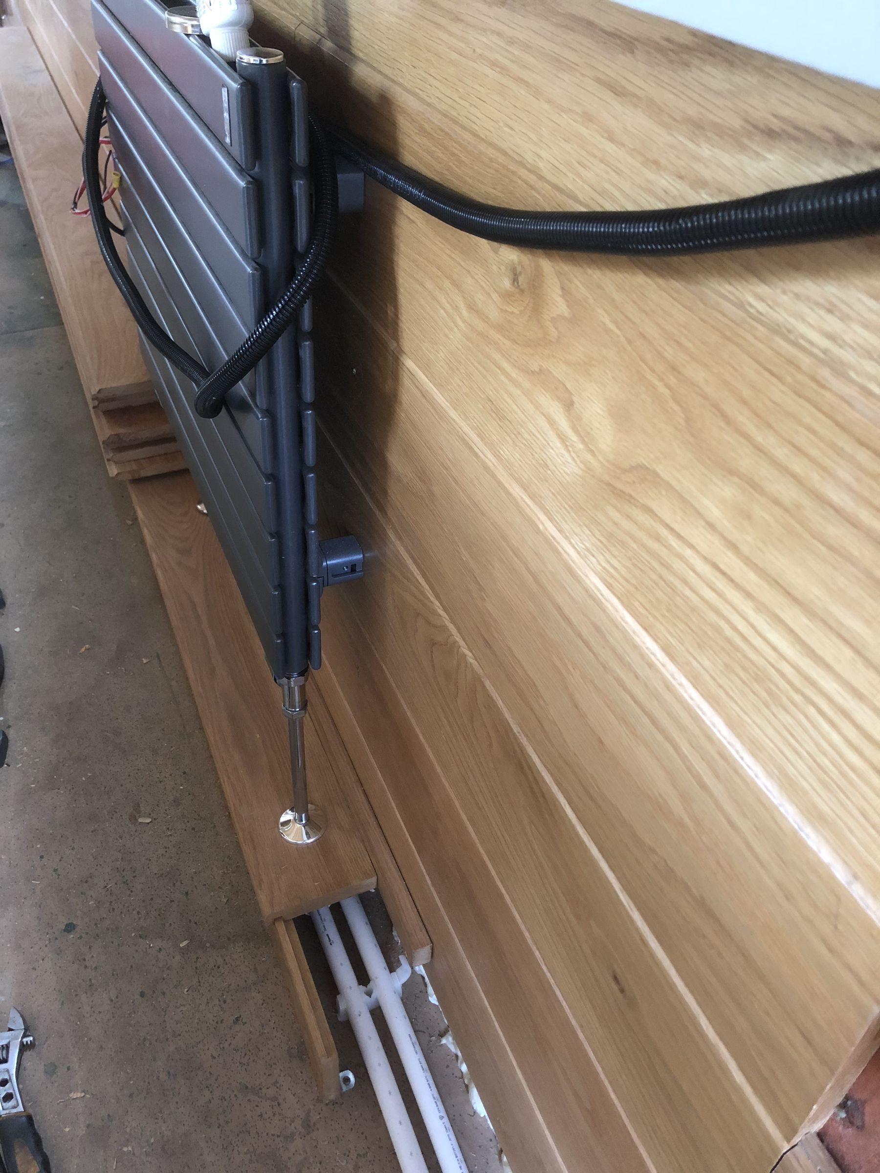
Does the BSS allow a 10 mm diesel feed copper tube to run alongside the heating pipes left of the two plastic pipes and right of the upstand in photograph clipped every 12” or so
-
Great thank you guys the shaft is 1 5/8” so about right then
with everything else was a bit of a shock when fitting prop
plenty of room behind prop for folding chairs etc
Richard
-
On fitting Propeller to through shaft there is a gap between front of prop tapered face and aft face of through tube to stern gland of about 1 1/2”
This is mid engined so shaft from Gear box to through shaft is bespoke and cannot be altered I can recut key way in shaft and chop off end
So how much gab would be about correct between shaft and through tube
Also would a flexible coupling be advisable between shafts
thank you in advance
Richard
-
Thank you all very much for your input Crowther marine were unable to recommend a prop due to limitation on swing
Other company's were vague also As Daves is tried and tested although all criteria were not as my build I think I will go for the 21x19
Now has any one got one kicking around it their shed
thinking T Norris as supplier as fairly local
Thank you all again
-
-
Hi although not a Gardner question I would like to find out proper size for a new build 62' with 3LW AND 2:1 reduction box Distance between uxter plate and tiller Skeg is 24"
I have had e mails from various companies who all seem a bit vague some would not advise at all, nearest being T Norris who advise either 22 X 16 or 20 X 17 or 18 i would really like to get this right first time so looking to you good folk for your experience Thank you
Richard
-
I am fitting out a new build 62' with a 3 LW
The top of the Skin tanks are about 4" below the centrifuge pump After around 1/2 hour running 3/400 rpm the pipe work from pump around block and head up to Borman header tank are warm Skin tanks feed and draw are cold
Any thoughts on this
thanks in advance
-
Wood Auto still do parts for BS5 & 6 also for SL5 & 6.
I replaced my CAV 24 volt starter with a 12 volt unit from /startermotoralternator.com but keeping the 24 volt very good company excellent service
-
I have a 3LW The original air intake was alumiminiun and had snapped halfway down I fabricated a new one in stainless I don't know how to post photos on here but it looks nice
-
Thank you Steve I think so it has a pin like detector on the business end I don't know how to put pictures on here it's a Murphy Magnetic Tachometer Sender 76mm x 5/8-18 UNF
A.S.A.P Part No. 708855
Richard
Steamraiser2 All these calculations went way over my head and could not measure fly wheel anyway
I went to Gardner marine in Canterbury and they let me count the teeth on a new one You were correct 175 teeth Thank you
-
Thank you Steve I think so it has a pin like detector on the business end I don't know how to put pictures on here it's a Murphy Magnetic Tachometer Sender 76mm x 5/8-18 UNF
A.S.A.P Part No. 708855
Richard
-
I have the hole drilled and tapped 5/8 to 5/8" UNF and ordered the sender so would like to go down that road
Thank you though This is my first owned boat as been one of them there hirers for the last few years because we had a time share thingy We are hoping to be CCers come next summer when all fitted out
Regards Rich
-
Thank you all very helpful The 12 and 24 volt starter both 11 teeth the 24 volt used to skip there was an O ring between the shouldered plate I assume is for lining up tooth to tooth as the hole the motor fits through is not central When I took the 24 volt starter out half of the pinion was scuffed and inner half clean. measuring in to ring gear from plate and measuring pinion depth there was about 13mm difference so removed 8 mm O ring now catches every time
I need to know teeth number for magnetic RPM sender
Propeller
in Boat Handling
Posted
Prop is brand new boat has only been in water 3 weeks changing gearbox not an option no fouling engine revs are very responsive