Dave_Beard
-
Posts
11 -
Joined
-
Last visited
Dave_Beard's Achievements
")
Gongoozler (1/12)
0
Reputation
-
Hi all i just found this which might be of interest TSB-1001_wire_size.pdf
-
Thanks for all the input i will use 35mm to 50mm cables and connect my charging sources to the house bank. Regards Dave Beard
-
Its a bit weid the size of cable 25mm that seems right for the voltage and current but the existing cable between the fitted scr and batteries is only around 2.5 to 4.00mm max their must be a lot of voltage drop. For that matter my last boat only had thin 4.0mm cables between splitter and battery banks odd
-
yeah good ideas thanks i like those fuses that sit on the bat terms great idea what rating should i use and also i am warming to the busbar to as it cuts down on a lot of wires i am also thinking about cable sizes do you think 16mm2 is overkill when at least one battery bank is about 15ft away?
-
Hi Robbo i see your point and i will change the plan to connect all charge sources to the house do you think any fuses should go in any where on this charge circuit?
-
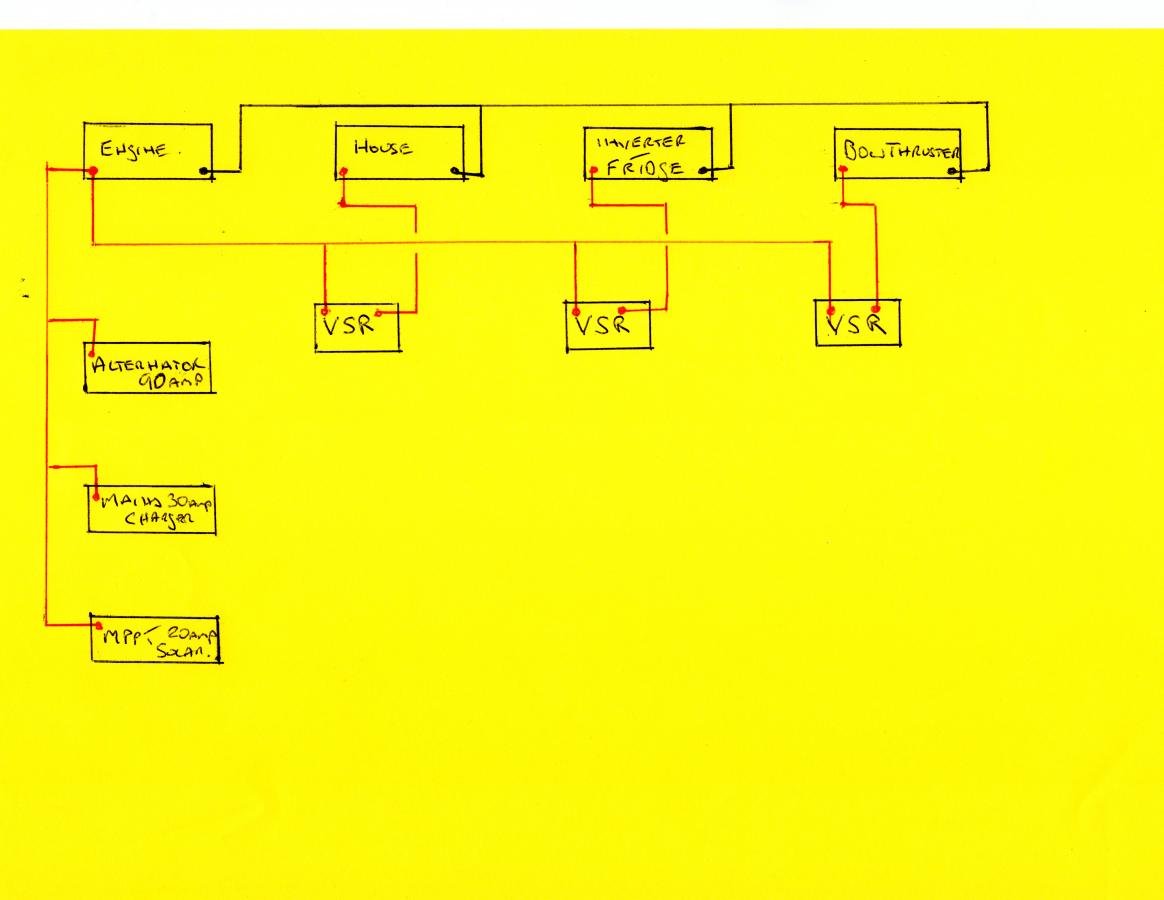
Hi thanks for suggestions here is my wiring proposal

-
I have four batteries in the centre of boat 1 start and 3 house then two batteries at the stern for fridge and Inverter and one in the bow for Thruster
-
Hi all my current split charge system for my four battery banks is a 90amp split charge relay 1in 3 out with the 4th bank being taken from one out to a conventional split charge relay also my solar panels are connected via controller directly to the house battery bank. I want to upgrade the whole charging system and my idea is to replace the scr with 3 vsr's and take the alternator, mains charger and solar charge all to the start battery and then use first vsr between start and house the second vsr between house and stern and the 3rd vsr between stern and bow does anyone know if there is a better way to wire this system up.
-
I have connected this inverter to my domestic battery and the plug top to my isolator switch and it works fine including also the test switch on the rcd so i am happy that i am fully protected.
-
Hi Nicknorman i have a double pole switch before the rcd unit that switches between shore and inverter but has a 0 isolator so no chance of trying to use both at the same time. I think i will just use the 230 volt outlet on the inverter and wire that to my isolator but i am not sure whether the rcd will work as there is no earth path.
-
Ok so i have read Gibbo's discussion from 2008 about how to identify the three main types of Inverter using his idea of a 25 watt bulb wired across the outputs and earth and have found my inverter to be of a type 1 ie no light on either live or neutral. So my question is now that i know it is safe to connect earth and neutral were should this be done and how somewhere between the inverter plug top and my RCD. Thanks in advance Dave Beard