


Jrtm
-
Posts
2,560 -
Joined
-
Last visited
Content Type
Profiles
Forums
Events
Gallery
Blogs
Store
Posts posted by Jrtm
-
-
16 minutes ago, Steve56 said:
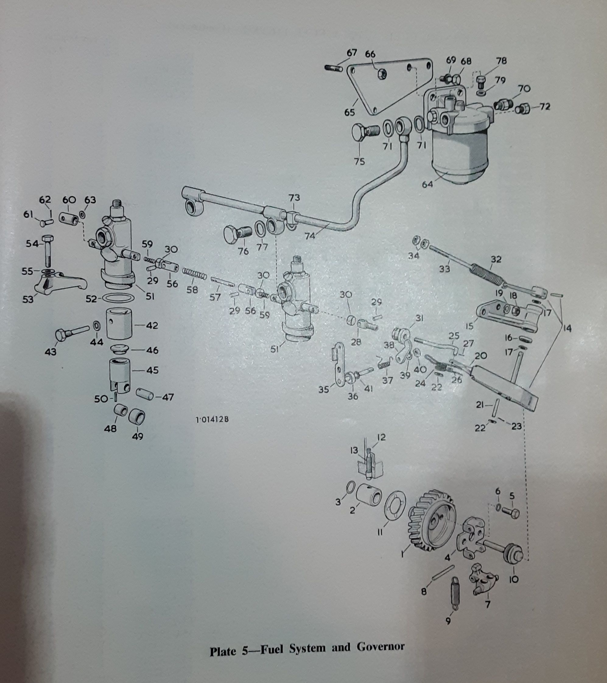
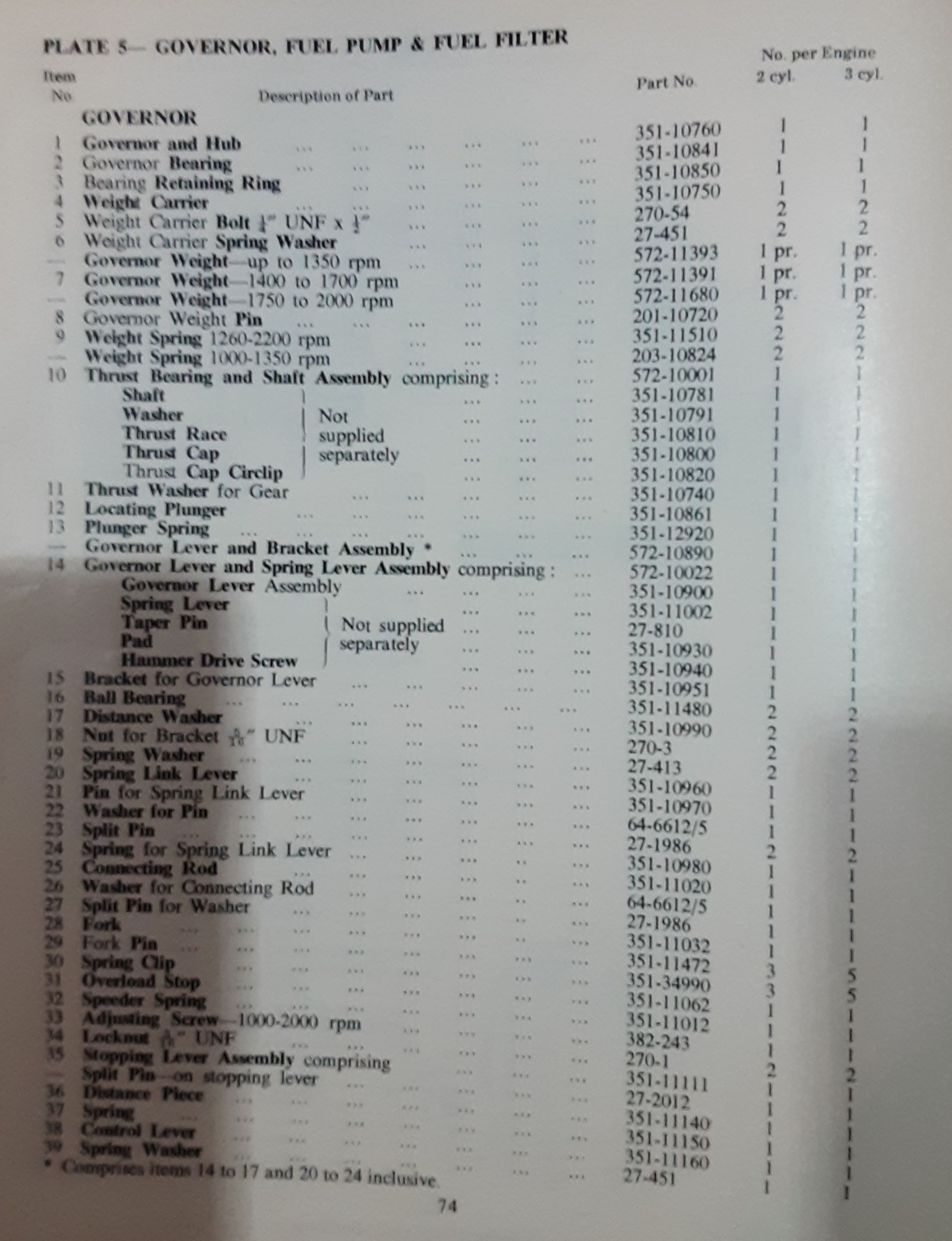
A little more info on governors which may help.

This is what mine is like 2 springs on the governor weights but your first says no governor spring if variable speed.
The bit I don't get is the fixed rpm vs variable, I get the weights ov limit the speed by only allowing the fuel arm to go so far and different weights alow different speed but if they have fixed speed surly it would only have a kill switch. Or do variable use 2 controls one for throttle control off the adjuster screw and then the stop lever?
Just confused as mine had an electronic controller on what would seem the stop lever.
I think the confusion comes in as every pic or info is for fixed speed not variable
-
Ooooo that's an interesting list!
Given mine over had a fixed 1500 speed but had a variable speed lever on it. Be it was electric controlled. But did have 2 yellow springs on the original weights.
I did order some 1800 weights but would pos appear they maybe fixed weights not variable.
But from that list it has now confused me as to how the weights work without a spring, oh well,
I'll have too try and find a photo of one thats not fixed speed. As the list above also show no speeder adjuster screw and assume the speeder lever only has one hole (not that that should need replacing as looks like the high rpm need it in outer hole.)
Looks like I can get the spring
-
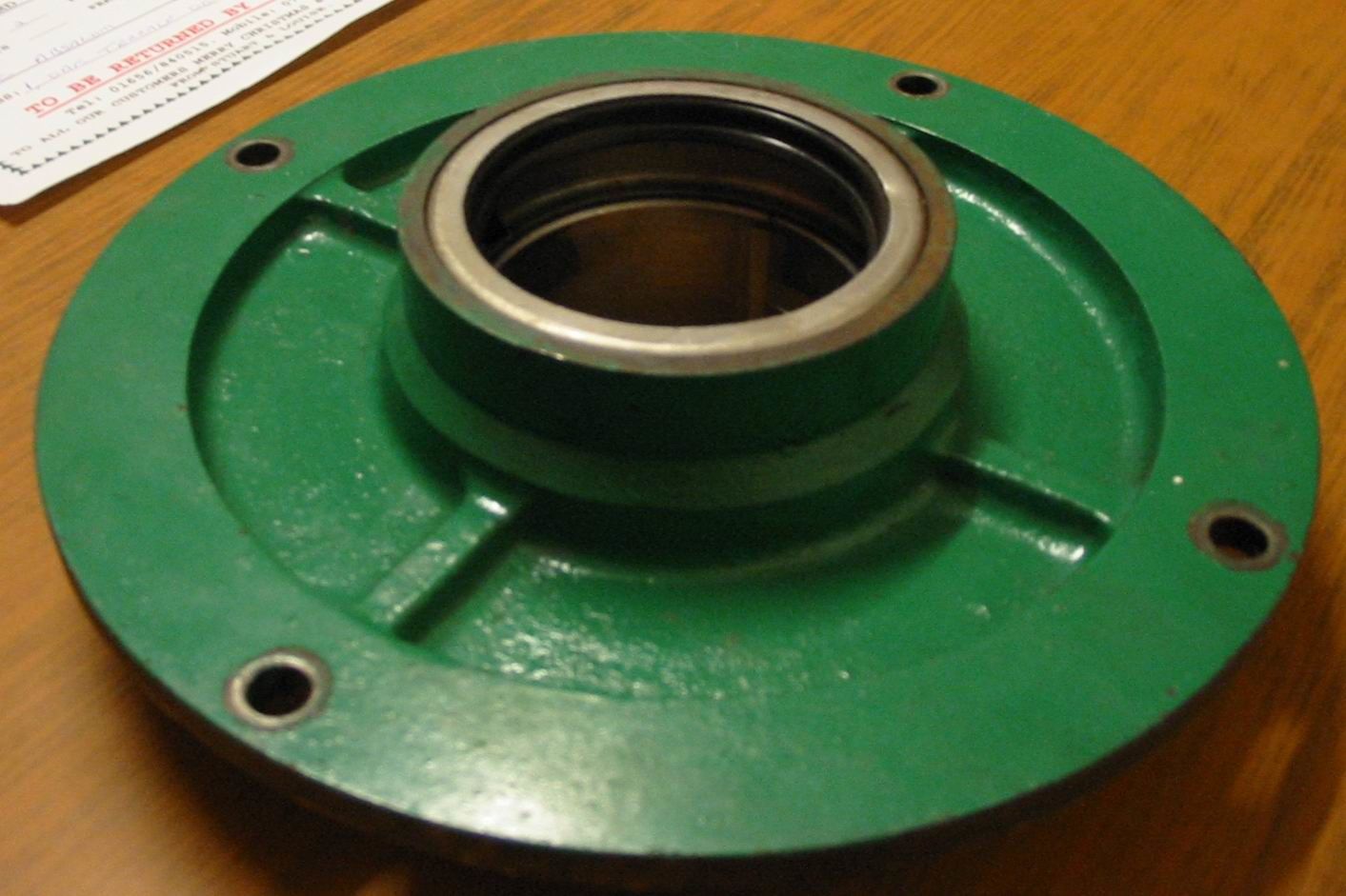
Thanks for above have new seal now.
I've stripped a bit more off all timing gears removed, fuel housing and fuel pumps removed, looked at camshaft and looks really good, I've looked at the gears and there is minimal ware on the gears.
One thing I did find was the shaft from the governor lever control levers to the fuel pumps has a slight bend in just at the end of the thread (not sure if this should be there or not but will get a new one)
Also found the governor weights had been welded didn't look normal I've got a new set of 1800rpm governor weights. Is there anything I need to change to go from 1500 to 1800 rpm? The governor tensioner spring and adjuster bar look ok again is it worth changing too? Its already got variable throttle rather than fixed.
-
I saw this, thought was a bit high for a marine engine conversion when there was one for sale a while back for that with box and with some history too
-
11 minutes ago, OptedOut said:
You could measure up the housing and shaft and bore out for a modern double lip seal.
Good shout, I'll be getting a full gasket kit but didn't think it had seals in, I should have thought of that given that's what I did on the national.
The ha isn't leaking but if its apart its better to replace
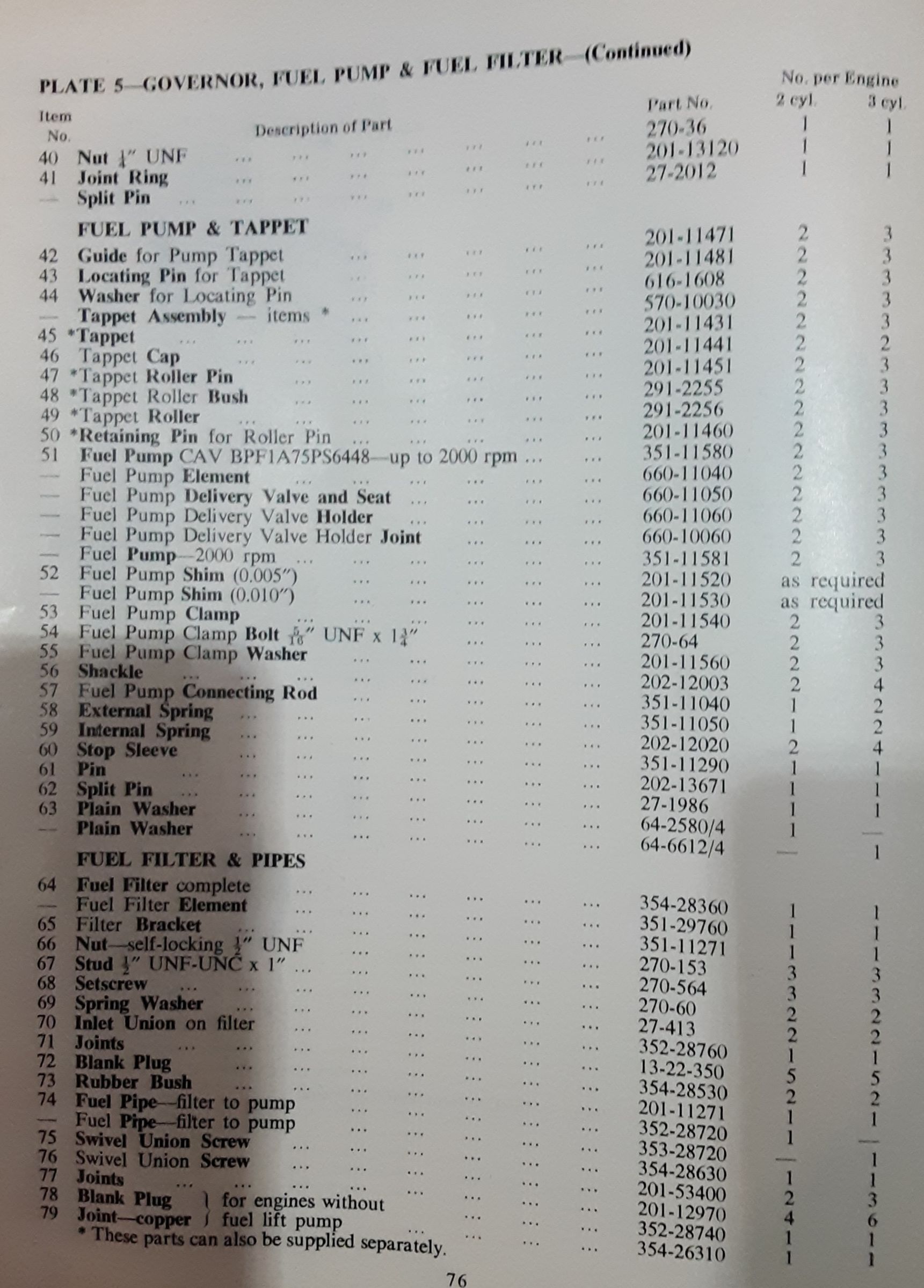
-
As its on the same engine, anyone know the part number I need for the crankshaft seal flywheel end?
As I'm converting to marine with 2g box I don't need a seal on the other end as this is an open end
-
44 minutes ago, RLWP said:
Ours are fully rebuilt and set up, you'd get two for £150
Richard
Far more sensible price at £75 each fully rebuild, one of mine cost £160 just for bits but as said I've only kept rack and housing rest is all new
-
One of the pumps is a cav bpf2b and another is bpf4b there singles are bpf1b
-
1 pump is a twin pump (1 single long rack) the other is 2 indervidual pumps with the rack bolted together,
As I'm stripping the completely the brass part the rack runs on won't be set into the correct position on the barrel, if the rack is fully to the left the brass part might be in a different position to the other. To set this up there is normally a dot on the brass bit and the barrel this brass bit goes onto but for some reason my new parts don't have this, that means if the rack is moved fully to the left (shut off) it might not be shut off, adjustment of the timing isn't going to fix this the pump needs to be set in the correct place first. This is what I have to set on the bench first.
If I copy a good pump I can set this into the right position. If its in the wrong position I could end up with over or under fuel compared to each other.
-
Hence why I wanna use a good pump so I can semi set the rebuild pump up as on a bench it doesn't matter when the timing is as long as the amount of fuel is the same at a given rack position.
As originally I was hoping to use a proper bit of kit for this but I'll have to make a home build one.
-
Yes, we're both on the same lines as to how to time it,
The timing marks for a pump stroke is normally in the manual, I know mine should be at tdc the line right at the top of the window and bdc should be at the bottom of the window think one of the engines should have a 1mm gap at the top. Realise this must be set on the engine as is on rods or some have shims.
But if the pump isn't setup I could have 1 injector pumping correct fuel and other too much or to little, Ill have to do this off the engine by making a bench tester so in a perfect world if I get the pumps the same then put on engine aslong as the gapping at timing is done correctly both injectors will see the same fuel and a given rpm
-
You must be able to set the pump up without being on the engine otherwise you would have to send your engine off when you have a pump calibrated if you sent it off. You normally have a set gap or point the pump is adjusted to on the engine, my engines have adjustable push rods and the instructions give a state as to where the pump marks should start from and go to.
I would send pic but I can't get one as I'm unable to get to the engine.
As my pumps are being fully rebuild every part new except housing and the rod, they would need all parts adjusting hence I need a good untouched pump to get the settings from as I won't be able to just adjust 1 tooth on rack it will need adjusting on the brass bit the rod moves.
-
My plan was to put them on a bench with a frame over which the pumps will sit on and is clamped to the frame.
Under the frame ill put a leaver system in so it has an adjustable push rod that sits onto the bottom of the pump and attached to a lever, ill then have a stop point so the lever can't pull the adjuster away from the bottom of the pump and ill then use the gauge on the pump so when I pull the lever down it pushes the pump plunger in and have a lower adjustable stop point on the lever so each lever can be set to the same stop point on each pump, this way will insure each stroke is exactly the same (in theory giving each injector the same amount of fuel once adjusted)
Ill set this up using a good untouched pump the put on a pump thats been messed with. Ill set up an adjuster on the fuel adjustment rod so I can test the pump at say 4 pre set intervals, fully off, fully open and 2 set points in the middle.
If I use your idea of making the fuel pipes drip into a calibrated glass after say 10 strokes of each I can see which injector pump needs adjustment comparing that to the good pump I first tested.
Most of my pumps are either singles or a double pump (the doubles run as indervidual pumps but in a double housing) and the cam for them is build into the engine not the pump.
This way I can have a idea of how much fuel each pump should give out for a set stroke using the gauge on the pump itself even with a bit of wear the line on the pump can still be matched on each pump, with a pre set amount of throttle, ill then match each pump to a good pump.
-
The pumps have a calibrated line into a slot i can a make a lever to fit and adjust under them like the stock push rods do so I can then get the same stroke from each pump.
I might not be able to so I may end up having to send them off, but as I have 5 I can play with one or 2 and see what happens, but I couldn't find a tool to do it but as you gave me this info above I've then looked and won't be able to buy one lol.
Hence seeing if there is a semi easy solution, as said I have a good untouched pump I can also test to see what this gives me, I also have old fuel pipe so I maybe able to create something to flow into my leak off containers.
I did look at pics which is why I've thought of a way I can make the pump pump.
As said if its not possible it will all have to be sent off once rebuild
-
I think you miss understood or me not explaining properly, its not a problem putting injector onto pump or activating the pump, its getting my calibrated diesel leak off pipes onto the end of the injectors or if I could find one getting an accurate flow gauge so I could fit a gauge to each output of pump to measure the output amount of fuel to then adjust.
I have a copy good pump so each one I know what the flow rate should be at a set point of the arm,
Due to cost of a machine I was hoping to put a inline flow gauge between each injector and the pump, and then also test how much fuel I had in each tube after the injectors. Again I can or will have calibrated injectors so thats not a problem,
As there old push style pumps they will all have the same min and max stroke on the pump.
-
34 minutes ago, Tony Brooks said:
The way Hartridge do it is to connect the pump outlets to special "injectors" venting into a set of calibrated glass tubes. The "injectors" are fitted with some kind of electrical contact that reacts to the injection pulses and that is what triggers the sparks.
Those glass tubes are in pairs on either side of the rotating metal plate so one set is always upside down. You run the machine and watch the fuel build up in the tubes. its easy to see which needs more or less fuel so you sop the rig, adjust the elements and turn the tubes over so the full ones drain and the empty ones are ready for use. You do this countless times until you get each element delivering the same amount of fuel.
Yes this was my understanding, I can do it in a sim way but I can't find and accurate enough digital reader, I have a fully recalibrated injector so I can test it from injector or directly out the pump but the only accurate gauges I can find are diesel leak test gauges (already have a set) but its not an easy task to connect to the injector nozzle or pump, was hoping to find a digital gauge I could connect to the pump and read it threw the pump
-
30 minutes ago, RLWP said:
HOW MUCH!!!??!!
Yes I got quoted 150 by a few people per pump to test and adjust after full rebuilds
-
Yes I'm getting the feeling I can rebuild them but not test them accurately enough, I could rig something up so I can test a good one the setup a rebuild one doing several different tests of flow at different rates of pump arm length but getting an accurate enough gauge is very difficult as your talking next to no flow at each pump, pumping the pump isn't a problem as I can rig up a way to pump the pump just not measure its output
-
Sweet cheers guys ill have a look, I don't mind the time but 5×150 is 750 so at a few 100 extra ill have a look, I'm not desperate but thought it was worth looking into.
I've got all the internal part numbers, for all the bits and I've got hopefully a spare full pump on the way (stupid covid has prevented me from getting up to York for a day trip out)
-
As above I've got about 3-5 pumps about all engines ran ok on them but will be doing full rebuild on them,
At £150 a pop just to have them checked after rebuild there must be a system or kit etc for setting them up.
I understand how they work and know how they adjust etc I also know some have collar setup marks on for the internal shafts.
I get to far moved around and they will put in different fuel amounts, I understand the rod and how it twists the internals to alow more or less fuel threw at different set positions. Given you can buy all new internals does anyone know the bit of kit I need to set them up.
I'm in the middle of getting a good injector tester to setup these after full rebuilds, and yes some pumps I can just exchange for a rebuild pump at £70 for lister ones but as I'm going to be doing a few I would much rather buy the kit I need.
-
1 hour ago, RLWP said:
You need to put the top ring into a clean ring groove, then put a feeler gauge between the side of the ring and the piston. As the piston moves up and down, the ring wears the side of the groove.
Richard
Got a piston grove cleaning tool already setup on lathe for doing this, just need to get the piston out, its all setup from when I did the national engine pistons, ive got a new set of genuine lister ha rings on order and as soon as they arrive I'll strip and test the piston ring gaps, but rest of piston is all OK and as is genuine ill reuse if they can be. If not if there is room ill have the ring groves recut and diffrent rings put in, if not it will get new 10 or 20 thou oversized pistons and have the liners bored to them to match
-
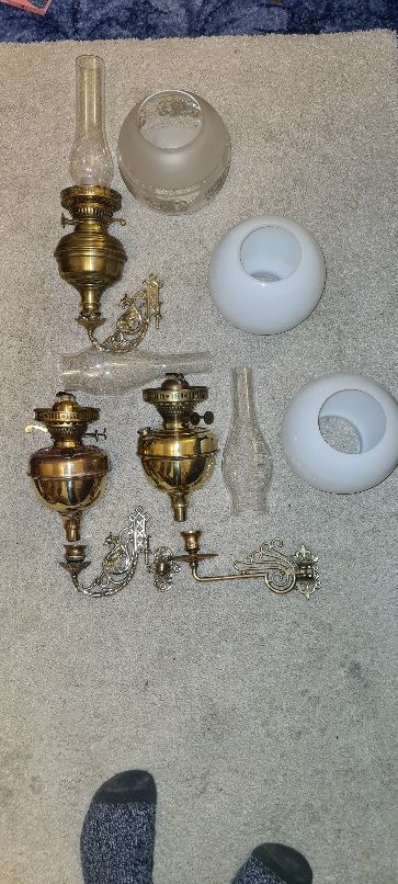
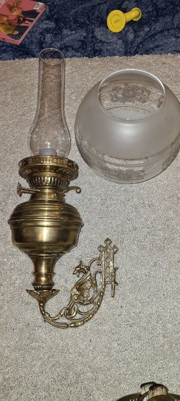
Just looked at chimneys 1 has a Welsh style draggon on the other says fire pro with an a anchor on.
The one I'm keeping is unmarked
-
Thanks for the info.
I was looking around 50-60 a lamp.
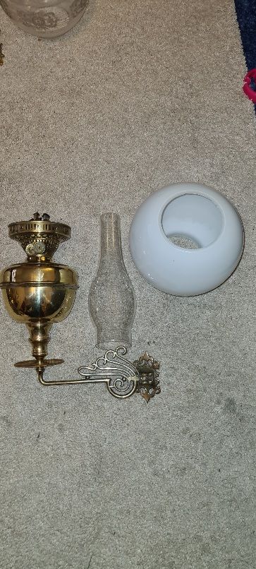
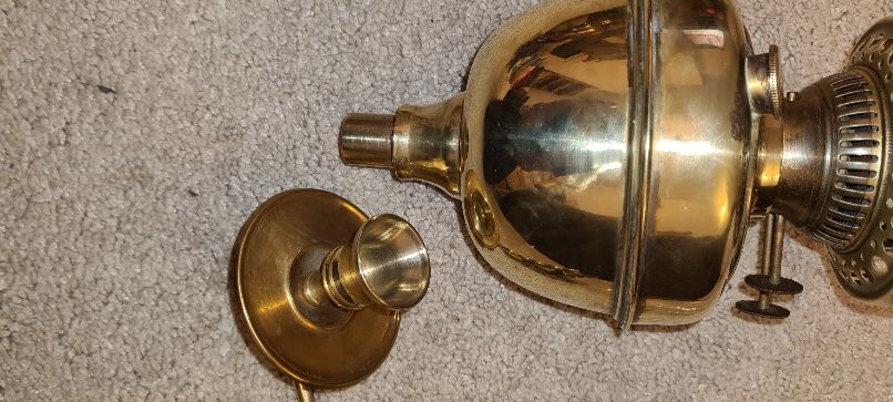
The one I'm keeping i do have a paraffin burner duplex again with matching oval glass but it will be one of the very few items I use that won't be paraffin day to day as ive learnt its a faf in back cabin trying to find way in dark then lite the lamp then find its empty ect, so as said this has already been electrified but has the electrics coming out threw the filler and down the Griffin in yellow gold wire to hide it a bit more. It then has a led bulb in.
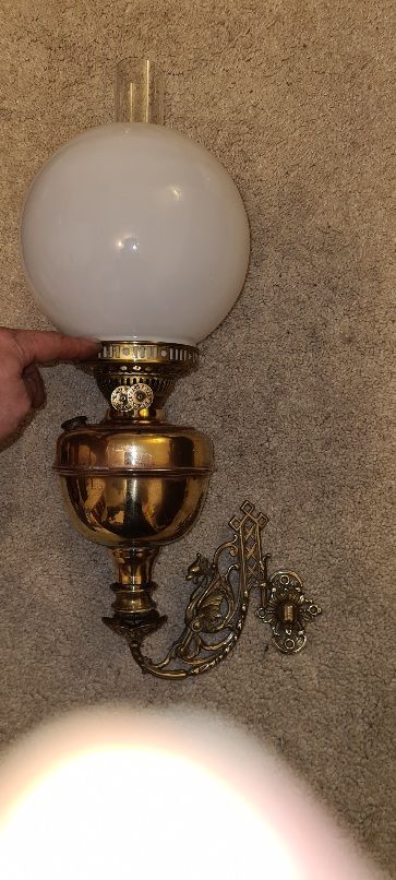
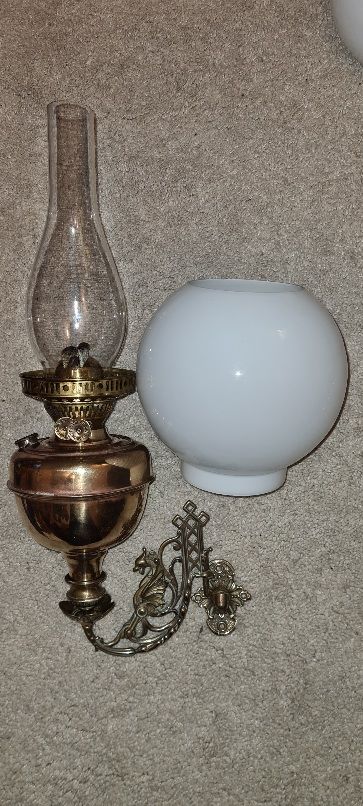
The other 2 as can see a still paraffin.
As say price i know a few years back they went for silly money same as everything ive got i just sit and wait till item comes up at reasonable price, that way if I sell on i just get my money back and someone gets a good item at good price, + if prices are too high they become too wanted by there's
Thanks for info though good to know there are knowledgeable people about.
James
-
The one with clear glass is the one I'm keeping for towy as its modded to be electric and paraffin, I've mixed them around a little due to my preference, but the 2 bodies that match with white globes and the griffins are the 2 I got together the 3rd is a modern bodie but has an old globe. I've then had to resolder and mod the base as they use to be very loose and wobble so I removed the wobble but they all just slot in and out as should
The swing arms are very solid brass, the white globes are very delicate there is a name on the chimneys but there very faint and again very thin glass.
I have no idea of age the one I'm keeping as said is more modern and in flesh you can see this but its still good quality unlike some, the others are a more basic design but are older.
I don't think there early ones but there not modern 2000 ones prob more like 70s?


Lister ha2 industrial to marine.
in Lister
Posted
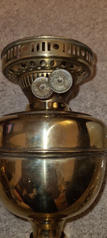
Yes I'm semi with you, as I do have a downloaded manual so with your lists above and this manual (has a close up of the governor weights) its how the speed is controlled and the governor adjusting screw work on variable.
Do you set the governor adjusting screw on variable to the desired tick over. Then use the (stop lever in the above pics) to then control the speed?
My manual just shows a control lever but dosnt show how its connected
I can prob get hold of the correct weights I did find what would now seam like variable weights and the spring I can get.