


Kingsford
-
Posts
7 -
Joined
-
Last visited
Content Type
Profiles
Forums
Events
Gallery
Blogs
Store
Posts posted by Kingsford
-
-
On 11/12/2015 at 14:25, magpie patrick said:
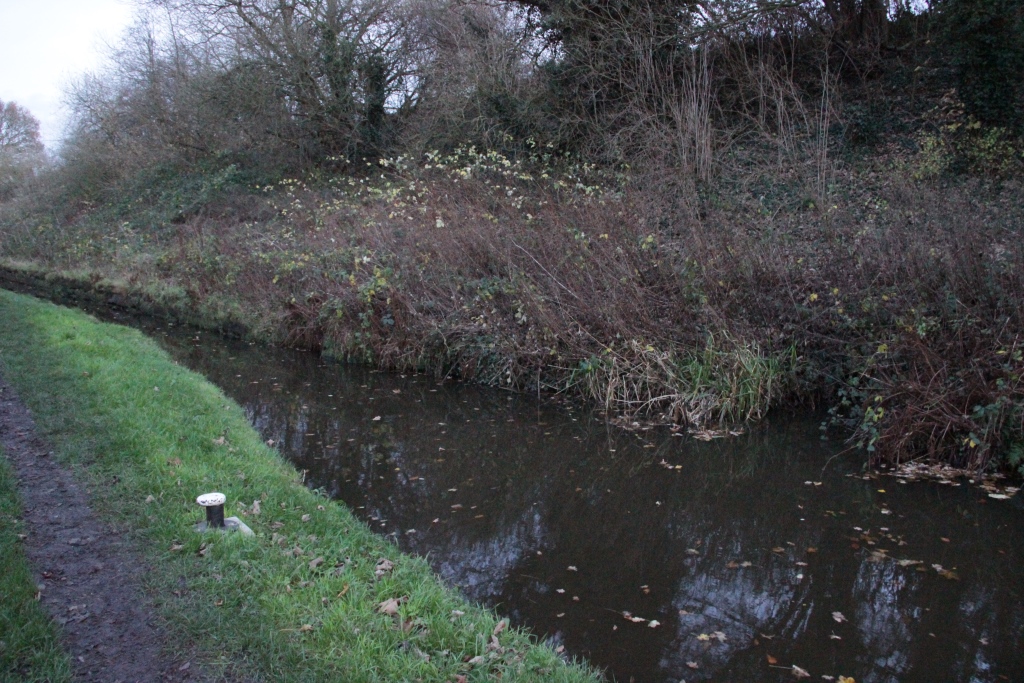
Finally, for this post at least, the sharp eyed may have noticed a bywash on the left of the first picture - this is the other end of it, to the right of this picture.

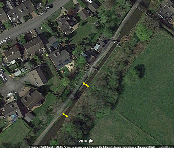
Another quick question, do we know where south of the two locks the outlet is for the water that goes over the bywash/overflow/waste weir?
-
11 hours ago, Heartland said:
If Kingsford would like to email me at rayshill2 [at ] gmail.com, I will see if there is a way to look at his question
The email address does not work.
-
22 hours ago, David Mack said:
Since the junction is at the bottom level of the Macclesfield Canal, occasions when the Macclesfield was lower than the T&M must have been infrequent. But the T&M lock would have protected the T&M in the event of leakage on the Macc, or a breach or even draining of the Macc for maintenance.
That's what I kind of figured, and I figure that during regular operations that the doors on the T&M lock were probably left opened most of the time. Also, since it could be operated in either direction, does that mean the southernmost and northern most gates in this chamber sat on a sill so they are both "upper" gates? What of the area in between the two locks?
BTW, any current examples of canal junctions like this which still operate where either side is higher? Would love to see some profile drawings like Pluto just posted to be better able to visualize their workings. Someone's got to be able to mock up a profile of the Hall Green lock chamber in Paint, or something, and it'd be a nice reference document for future questions.
Honestly, I'd message someone about this so as not to clutter the thread, but it says I need 10 posts to do this.
")
-
1 hour ago, magpie patrick said:
It is not that unusual for stop locks to have four sets of gates - the one at the junction of the Ashby Canal with the Coventry did for example, what is unusual here is the double chamber.
Edited to add, the stop lock at the other end of the Macc, in Marple, had four sets of gates so either canal could be lower than the other.
You should also note that as built the summit level of the T&M was approximately level with the Macc - at some point the T&M was lowered by about a foot as mining subsidence had reduced headroom through Harecastle Tunnel (and increased depth!) This means the purpose of the structure is less obvious.
The term "stop lock" refers to a lock that is intended to control the flow of water between canals - they tend to be shallow although lock 20 on the Stratford Canal, which for a couple of centuries was the junction between it and the Grand Union/Warwick and Birmingham, is around 6 feet deep - the W&B had a right to full lock full of water with every boat, and this lock ensured they got it (and no more)
48 minutes ago, David Mack said:The setup comprises two locks of conventional form except the rise is very small. The key point is that they face in opposite directions.
Most canal stop locks consist of two sets of gates.
Thanks, everyone, for helping me understand what was - and wasn't - unusual about this particular lock. BTW, what are some scenarios in which the T&M would have been higher than the Macclesfield? Just regular weather events, leakages, etc?
David, from an old drawing I've seen, the T&M's north/south or up/down lock gates were just single gates and didn't "point" in either direction. The only pointed set of gates seems to have been the northern gates of the Macclesfield stop lock.
-
13 hours ago, David Mack said:
If the Macclesfield level was higher you would lock down through the Macclesfield lock then pass straight through the T&M lock, and vice versa if the T&M was higher. Either way the only water transfer between the two would be a very shallow lockful. Without the stop locks there would be uncontrolled (and unquantified) flow either way.
Right, I understand the basic purpose, and that would exmplain why the T&M manuevered to have the new Macclesfield install a stop gate, but doesn't explain the reason for then building their own stop backed right up to it, except for obvious redundancy in case something happened to the Macclesfield stop gate. And, maybe, the explanation it's just that simple (redundancy).
But, as has been discussed, this was a very unusual setup. We're talking two chambers with four sets of doors in which both locks could act as lift locks; in fact, it seems arguable that that was their primary function. Typically, these canal junctions would only have two doors, correct? I think the other thing is that when we're talking about a "lock" we're usually talking a pound enclosed by two sets of doors to provide a rise/fall, whereas a "stop lock" is just a gate, right?
-
Sorry to bump what is such an old post, but I've had questions about Hall Green that I still haven't quite fully found a good answer to. Some of the confusion may be how terms are being/have been used (is the "stop lock" the water in between either of the gates, or just the "down" gate on either lock?). But, just to describe the setup in the overly-long chamber from north to south you had a set of pointed gates, then a single gate, then a small gap in between, then another single gate, and then another single gate at the entrance to the T&M side? Did I get that correct?
From the various pieces I've read on this, it seems that the purpose was originally to keep the Macclesfield slightly higher to 'protect' the T&M Hall Green branch. And, if that was the case, the Macclesfield lock really just functioned as a lift lock. Anyone have any of the original documentation organizing the development of the canal? The Macclesfield website seems to at least imply that any lock where the two met was simply to prevent water loss from the T&M. But then you see mentions all over that "either canal could be higher." This seems to skip right over in time the explanation for the development and purpose of the T&M lock. But we know that it was needed for one reason or the other, so I guess them both functioning as lift locks would make sense.
To end, a boat traveling "down" the from the Macclesfield would be locked down into the Macclesfield lock, and then in the chamber the three other gates would simply be opened - after they paid their toll to T&M - to allow passage? Is it that simple? Would kind of like to see someone make a little diagram describing how this setup worked.
Hall Green Stop Lock
in History & Heritage
Posted
Ah, yes, I see. I completely misread the post; happens to the best of us.😅