


GBW
-
Posts
117 -
Joined
-
Last visited
Content Type
Profiles
Forums
Events
Gallery
Blogs
Store
Posts posted by GBW
-
-
The ammeter is below (and the cockpit mounted repeater not yet fitted) but all that would show, I think, would be intermittent charging with a flickering needle (which I would probably ignore!).
I have a bunch of clip on thermostats, penny sized, intended for coolant temperature monitoring but one adjacent to the starter may well have been effective.
-
The shroud I referred to is internal - black in the photo.
Using a bit more courage, the body did pull off.
The tag connections to the coil will need unsoldering I think to allow removal of the cap.
However, with a bit of luck and using the invaluable advice from you and MtB, I might get away with swapping just the body. There is no reason to think the motor has been damaged.
This seems to be the cap;-
Thanks to both of you.
-
Access on sea-going boats varies. I sailed with someone on his 47 foot ketch and become convinced that just after the keel was laid, the bed were installed, the engine mounted on them and then the hull was completed around it! Access was virtually nil and the engine needed to be lifted for repair.
On the other hand, some boats have engine spaces all around them. Mine lies in between but, inevitably, the oil filter and starter motor are down the "wrong" side!
Fire on boats in general is very rare but when the engine is "below", evidence takes longer to reach the helmsman. When we arrived at Tenby dock, two fire officers were waiting. They performed a pyrotechnic inspection of the engine space using a hand held device. Perhaps such a device exists for a permanently mounted operation. Temperature sensors are generally fitted but normally on the cooling system. I would never (previously) have considered one at the starter motor. I may change my view!
In the many cars I have possessed I can't ever remember checking the connection to the starter motor.
Incidentally, that was the second "loose nut" experience on the trip. The first involved a through bulkhead connection where 5 volts were lost from the (different) alternator to the batteries due to a loose nut. It is now a loctite nut.
25 minutes ago, Tony Brooks said:I have never found a BMC 1.5 starter where you could not separate the whole solenoid from the starter, but I suspect it is just the plastic cap that needs changing. However, I have seen caps that are swaged in place rather than held in place two screws. Any chance of a photo.

The spare starter I have is in working order and I am reluctant to wreck its usefulness by an unsuccessful dismantling. The access to the solenoid on the boat is relatively simple. Two of the three bolts securing the starter are visible and accessible. The third is below and difficult, although I seem to remember in the dim and distant removing and replacing it for some reason.
Visible in the photo is an internal rubber shroud. extraction of the operating armature is now reluctant. Perhaps I'll try pulling the motor armature next. Would removing the operating pivot pin be helpful?
-
A warning to all!
I am cheating a little as my boat only spent a year on a canal (The Gloucester-Sharpness) and is now sea borne but this forum is invaluable for information on my BMC 1.5 engine.
A salutary warning.
Sailing from Milford Haven to Worms Head under power (no wind) to await the tide, when 8 miles off I went below to update the log. Checking the engine for water temperature and oil pressure I was greeted by flames.
These were extensive but succumbed to CO2 and water.
Although yet to be confirmed, the cause seemed to have been the alternator output connection to the starter solenoid. This, as in cars, is a direct connection perhaps for convenience.
I was unable to stop the engine with the stop solenoid (an unrelated fault referenced previously) but the CO2 finally did so. I could not subsequently restart.
My suspicion is that a loose connection at this point caused resistive heat eventually sufficient to ignite adjacent flammable cables and hoses.
The solenoid is wrecked but the motor may be ok. My on board manual tells me that the two cannot be separated. Back home, looking at my spare, I believe this to be incorrect. Time will tell!
I return to the boat tomorrow (in Tenby after a tow from the lifeboat) and will update.
What do others do to detect fire? There was surprisingly little smoke.
-
There is no matching slot on the gasket. The oil feed is through the circular boss.
The slot appears to be redundant.
-
And the slot?
-
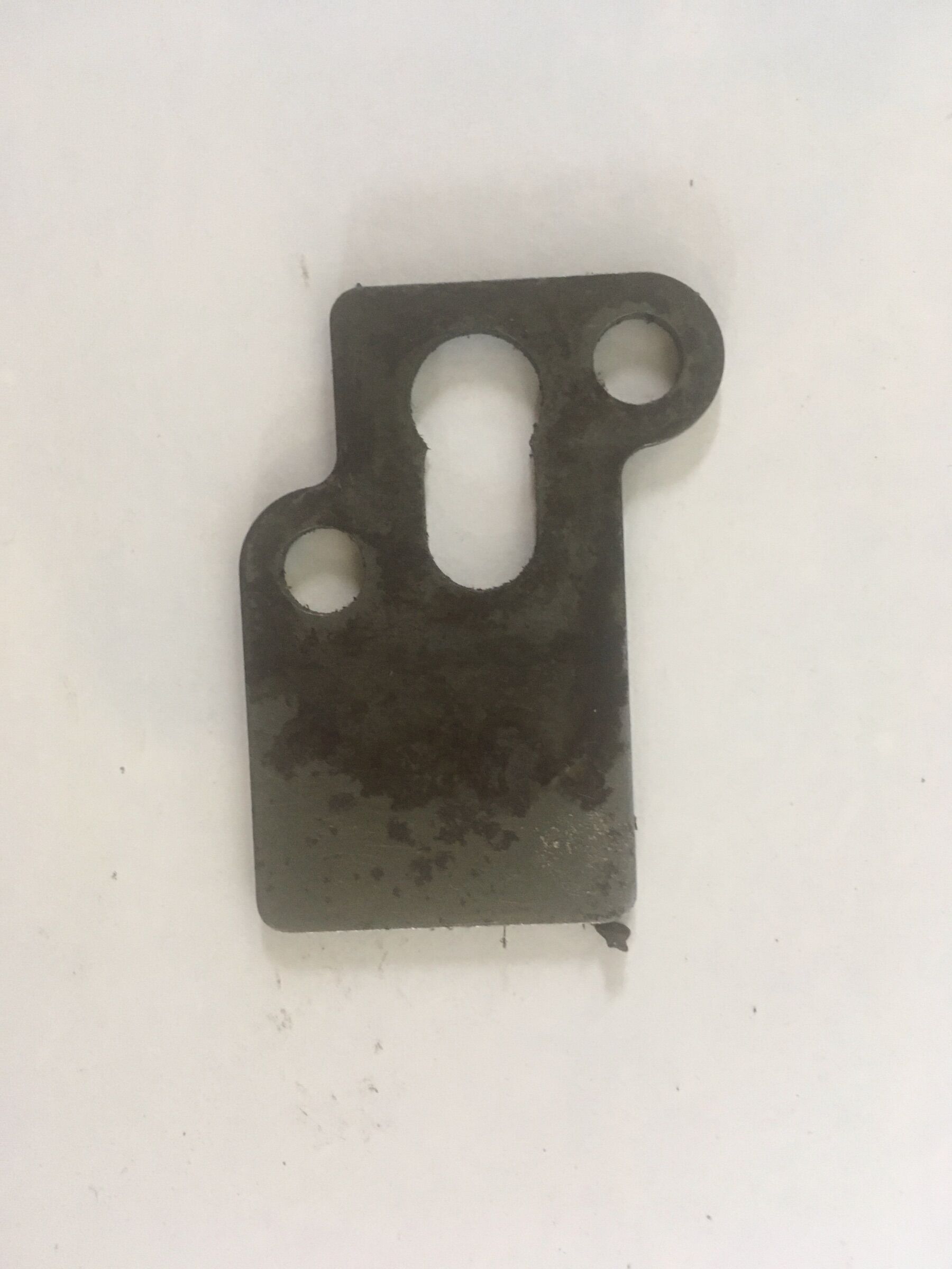
The three circular holes exactly match those on the chain tensioner but the slot has me baffled.
-
What's this? I can't find a location for it. The length is 50mm (nominal 2"). None of my manuals shows it. (Could be off something else and infiltrated the rebuild bench 🤫).
-
Thanks for your response confirming all I have discovered laboriously elsewhere!
There are two water connections between the cylinder block and the head. The joint is made with two high temperature O rings. Both these on. my engine had disintegrated. That joint could provide a route between water and oil although somewhat tenuous.
-
No, it wasn't Calcutt!
-
Don't ask me who supplied the engine!
-
28 minutes ago, Tony Brooks said:
Probably, but they always come out a bit flatter than when they went in.
The two references I have (one courtesy of Tony) show the atomiser washers either point up or point down. It would seem not to matter.
Much more importantly, they both show the presence of a washer (copper?) on the end of the injector. I expected to find one such but did not. That would limit the insertion depth and also determine the loading on the atomiser washer.
Curiouser and curiouser.
-
I only changed the nozzle.
I can't find a figure for the torque setting for the injector hold down nuts. Presumably the atomiser washer does not end up completely flat. Is there some resilience remaining when the injector is correctly torqued down?
-
Thanks.
I only asked about removing the top hat to check if there was an atomiser washer present.
It seems that whoever rebuilt the engine, omitted the atomiser washers. I do not understand their function unless it is only to stop blow back.
-
I have in the past changed a couple of the glow plugs. I don't recall any difficulty.
I am sure the engine will appreciate warmer weather. It normally starts immediately.
-
Maybe that was why the injector was so difficult to extract. The injector does now sit higher than the others. Reason could be two atomisers in cylinder or none in the others.
On the spare engine, the injectors just drop in - a rattly fit and the gap between the flange and the head, with no washer inserted, is the same as the ones on the boat engine.
Is it possible to extract the top hat to be sure? Certainly they don't want to move on the spare head.
I haven't checked the others. I need to make something to ease the extraction.
6 minutes ago, Tony Brooks said:Agree with Tracy.
However, the poor starting may indicate some glow plugs have failed or they need removing and the carbon in the hole around glow plug pin needs drilling out. A well known problem with poor starting 1.5s.
As I explained, I monitor the current to the glow plugs and it was normal. I will check for fouling round the plug hole. Is there not a danger of pushing the carbon into the combustion chamber or will it just be blown out?
-
There was no atomisation washer in the installed engine (and no trace of a disintegrated one). Were they always fitted?
The spray from the injector looked excessive even though the pressure was correct. I replaced the nozzle with the new one (referenced above) which gave a much better defined spray. I refitted the injector using a new atomiser washer.
Being cold, the engine took a long time to start and then was very lumpy possibly due to remnants of air in the lines. When warmed up, it did seem to run more smoothly than previously but I didn't have time to run it long enough to check if the clank had disappeared.
Once the weather warms up, I'll try again and report back.
-
Would "crinkle atomiser washer" be another description for the fire washer?
-
The injector is without its shield. A peer down the injector hole on the spare engine shows me what your are talking about (you are right to query my knowledge Tony - but I am learning!)
Next time on the boat. I'll check the state for presence and condition.
-
Update;-
The wedge helped but it was difficult to get a decent swing at it in the confined surroundings.
I removed the studs and could tap the inject round (with a brass bar). Then it came out.
Back at base, the spray pattern looks good, both holes squirting and the pressure seems right.
I came to the conclusion a heel bar would be best. Back to ebay!
-
I remembered these;- They are wedges to separate a chuck from its taper. (The magnetic tray is there to enable standing one on edge). Although the gap is too small to fit around the injector, they reminded me that I have a piece of tapered plate that I can cut some from. Might be a useful idea for others.
-
Thanks Tony. Yes holes as you describe. The pin on one of the injectors for the spare engine was seized solid. I extracted it by holding the body in the lathe chuck and using a drill chuck in the top slide to pull it out. An hour with the ultrasonics seemed to fix it and the pressure and spray pattern seem ok.
-
(I thought I could edit).
I'm wrong - there are two holes (higher powered loupe!).
-
9 minutes ago, agg221 said:
Can you see that written on the side of the nozzle? It should be etched on the side.
Alec
Yes it is.


Fire!
in BMC
Posted · Edited by GBW
Repeating an ammeter in the cockpit (times 2 as I have two alternators) implies heavy cables with quite long runs. My intention is to measure the volts from across the existing cables with micro-ammeters. I have done this to sense the glow plug current and it is a boon. Fsd means four glow plugs drawing current, half full scale, two etc. The problem is finding meters with moving coil mechanisms as they all seem to be thermal (at least the ones I have found - it isn't obvious until you use them).
However, I have found some cheap (i.e.Chinese!) meters on ebay fsd 50 microamps which will do the trick. Needs calibrating of course.
The same meters will do for volts as well. I am a firm believe in monitoring - information aids diagnosis!
The thermostats I referred to are as these;- https://www.ebay.co.uk/itm/254292043897
All these things take time!