


GBW
-
Posts
110 -
Joined
-
Last visited
Content Type
Profiles
Forums
Events
Gallery
Blogs
Store
Posts posted by GBW
-
-
11/16" or 17mm "modified" with a bit of effort!
The first attempt used an open ended spanner on the nut. It couldn't cope with the torque.
-
Despite an extended search, I could not find an original hence my own attempt.

-
I have juat heard from MG Owners Club. The MGA and B head studs are 3/8" UNF but the MGC are 7/16". I have placed an order.
Thanks for your help.
-
The ring spanner is welded to a Ø10mm bar at right angles to the spanner shank. The bar length is ~60mm. The other end is welded to another socket end, Ø17mm on the end of the ring remains of the first attempt spanner, such that the two socket ends are coaxial. The top ring is welded to a scrap 1/2" square drive socket.
They do say a picture is worth a thousand words - I'll work on it!
The manual recommends a torque setting of 70 N/m which is pretty heavy.
I was wrong about the studs - they are 7/16" UNF both ends.
Don't know how to edit but this is similar;-
-
The fuel filter is fitted on the rear end of the engine (also the case on my existing soon-to-be-replaced fitted engine).
The bracket has two holes and the extra thick nuts to raise the filter(s) to clear the engine block.
I think you are correct about the thread difference. It is certainly the case with other head threads. I read somewhere that a coarse thread, UNC (but in my recall Whit) is a stronger solution in cast iron.
Thanks for the steer to spanner sizes. The site confirms my feeling.
I found a 11/16" ring spanner to fabricate a "joggled" spanner for the nuts buried under the rocker shaft. (The first attempt with an open ended spanner failed due to the high torsion involved).
-
Thanks Tony.
I buy my bits from MG Owner Club as the service is slick (and the prices low) but the spares website is a little light on the illustrations (and they had a website problem yesterday).
I have mislaid two head bolt nuts. I ordered what I thought were the correct replacements but received 3/8" UNF and thick washers (listed as 5/16" but actually 3/8".
Two of the head nuts are extra height, through threaded and the filter bracket bolts on top.
The OD of the bolt measures 0.437 which is 7/16".
Thanks.
-
What size are they? I believe 7/16" UNF but others say 3/8" UNF.
There are two "thicknesses" two carry the filter assy.
-
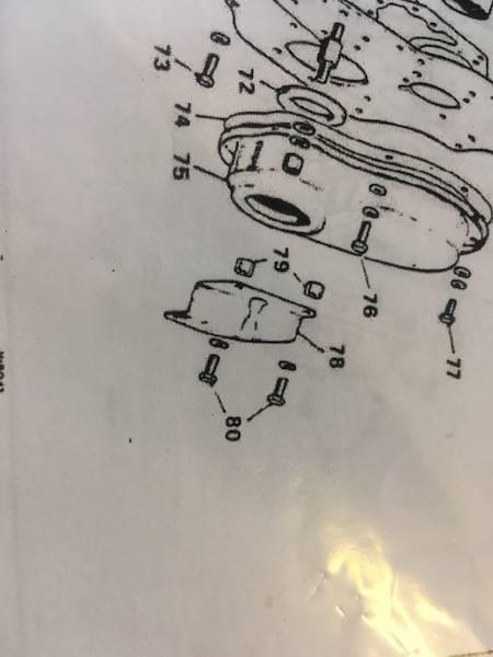
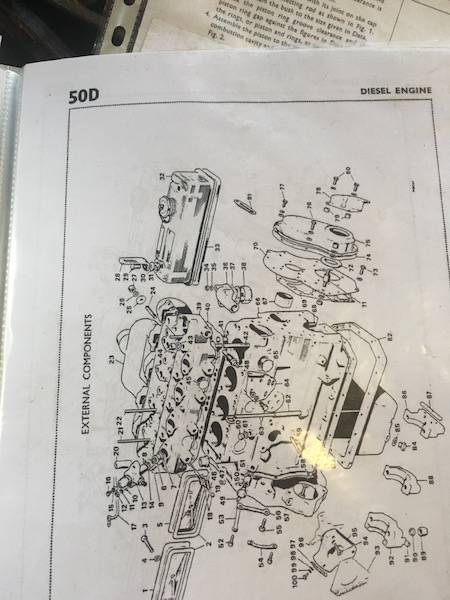
The sketch attached is taken from the BMC 1.5 diesel manual and shows a timing pointer, item 78, which looks the part. https://marinedieselbasics.com/wp-content/uploads/edd/BMC-1.5L-Workshop.pdf page A4.
I will order it and report back. I have made one but, if the supplied part is already marked in degrees, it will save effort.
-
I posed this question on the MG Owners Club forum.
I quote " the timing marks moved from underneath to pointing at the alternator, according to the books, changing in about 1968 with the 18GG engine."
That sounds like a possible solution but it implies that pulleys I found on ebay have the same arrangement. It woiuld be interesting to discover if there are two varieties of pulley.
I have made a bolt on joggled plate I can mark with TDC and 22° bTDC which should work.
Unfortunately, with the engine on the bench on a support frame, I can't mount the flywheel so the timing will have to wait a bit longer.
Thanks again.
-
I have compared the pulley with others (pictured on ebay) and the keyway and notch are aligned in the same way.
The crankshaft keyway is in line with the big ends which appears correct.
Obviously every other engine is wrong!
In desperation, I am making up a timing plate to bolt onto the cover and will mark it appropriately.
Tony's idea of using the flywheel as a protractor is excellent (and not one I would have thought of).
The mystery remains. If I find an explanation, I will post it here.
Thanks again for all the help.
-
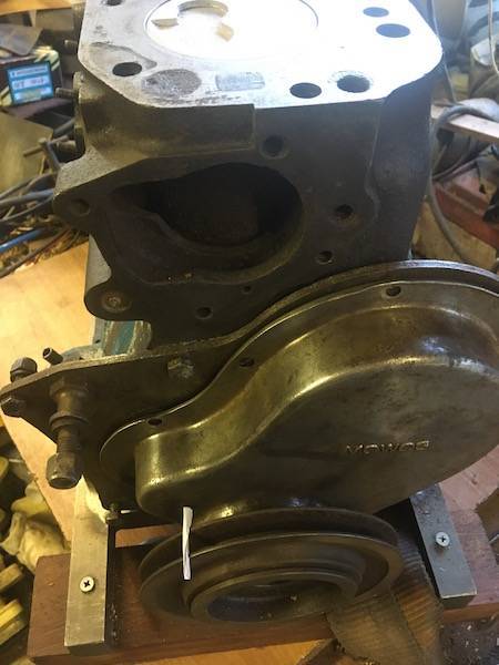
Photos attached. As you say, there is a timing mark on the chain cover (albeit a crude one) shown in the photo.
The other photo shows a white marker in the pulley groove and the piston is at TDC.
The botl on plate I referred to, is shown if the other photo which is taken from the !.5 manual readily downloadable.
-
Thanks.
-
Thanks to all.
Sorry if I have posted in the wrong forum. All my posts have been about this engine.
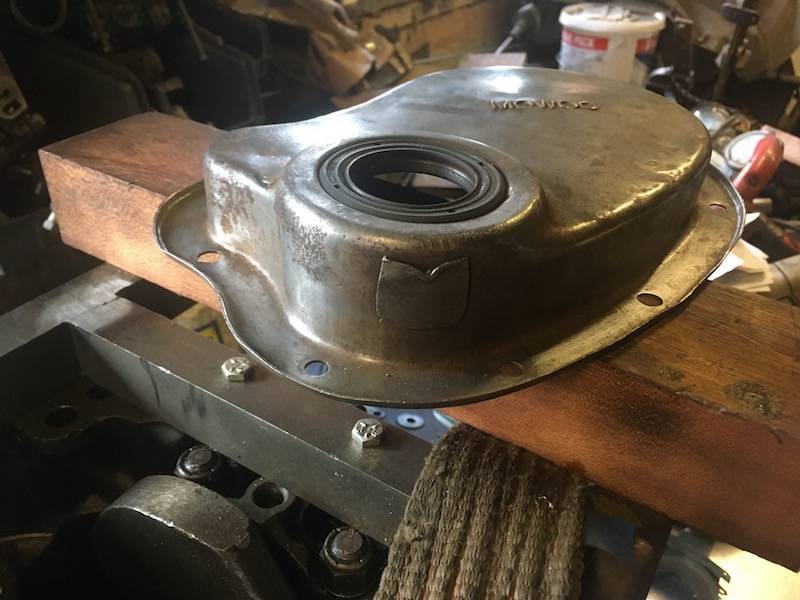
On the bottom of the chain cover, there is a rather crude minimal pointer. Lining the crankshaft pulley indent with this, puts the crankshaft near bottom dead cent. I have a Wolsley manual with the same engine and that shows a bolt on pointer with two fixing holes to fit over the chain cover.
The flywheel is not yet fitted but the head is off so I guess, if I make a pointer as the drawing I have, I can gauge TDC from the piston movement - half way between when it stops coming up and when it stops going down.
I use the MG Owners Club spares website as they have a large stock of engine parts for the BMC engines fitted to the MGA and MGB. (They are cheap as well!).
I'll take a photo of the Wolsley drawing and (hopefully) post it here.
-
(I know, it's taking longer than anticipated!)
Finding myself baffled trying to set the injector pump timing, I found the timing mark on the main pulley lined up with the pointer on the underside of the chain cover a long way adrift.
Perusing the various documents I have to hand, it appears there is a bolt on pointer which lives in a more rreasonable place.
During the closure of my engineering company, it seems to have gone missing.
I have not found it listed on the MG Owners Club site (which is my source for spares).
Any advice please?
Thanks.
-
Lit (for heat) or unlit for ease of combustion?
If the latter, would a cigarette lighter suffice?
-
My 1.5 BMC in benign temperatures starts fairly easily and, once warmed up, starts instantly, however, in current conditions, ~10°C, it is very reluctant even with one minute of glow plug usage (yes, I know they are working as I monitor the current).
Remembering the cautions about the use of Easy Start, I did try a quick squirt into the air intake and was amazed at the instant start resulting.
What are current views on the possibility of engine damage from its usage?
-
One of the "navvies" has managed to make contact with the aforementioned Sykes es employee who has offered to rebuild the pump.
Problem solved hopefully.
-
I now have a little more information.
Univac pump p1.pdfUnivac pump p1.pdf
I don't understand item 32. The only person left at Sykes with an in depth knowledge of this pump has departed (the company not life).
It seems the shaft, item 14, rotates inside the bush item 32. There are shim washers 22-24 which seem to allow the impeller to be moved back and forth relative to the shaft. Maybe these shims provide a seal but it doesn't seem right.
The other conundrum is that there seems to be no source of lubrication between the shaft and the bush. Can it be water lubricated? It is ferrous but no signs of rust.
The bush is described as a "renewable sleeve".
Today is "Canal Day" (the volunteers work on Tuesdays) and perhaps they have discovered more.
-
I am very much an outsider but I will attempt to find some more details, sizes and photos. It has a vacuum pump and electric start.
I have seen it working, lifting around 8 feet and an impressive output.
Thanks for all the suggestions. I'll pass them on.
Despite the enormity of the task, the volunteers are not overawed accepting that it will be their grandchildren who may see their ultimate rewards.
The canal having been taken over by a railway company, it passes through Newent station and there are plans to install an inclined plane to access it and cross a main road.
The other little problem is the tunnel under the M50.
-
 2
2
-
-
I attempt to support the Hereford & Gloucester Canal Trust in their ambitions to recreate the 34 mile link. (This is not a trivial aim!).
Our local stretch in Newent has reached a modest milestone with a short stretch now in water. It is filled from a local source using a Lister powered centrifugal pump. The engine is responding well to restoration but the pump seals have failed.
The problem is that it has proved impossible to find drawings of said pump to understand the sealing arrangements.
I can manufacture the parts but not without drawings.
Anyone help please?
-
Thanks for the head up. I think I made one - I'll start ferreting!
-
Thanks both - money saved!
-
Do I need to replace the cylinder head bolts with new? They seem pretty expensive but I don't intend to "spoil the ship".
-
In case anyone doesn't know already.
There is a lot of commonality between the BMC diesel engines and their petrol equivalents.
The MG Owners Club website offers many interchangeable parts at substantial savings.


Cleaning an oily engine.
in BMC
Posted
The new engine is ready to be tested (at home) and the old one is sitting at the top of the drive awaiting cleaning.
It is oily.
What is the best method of removing all the gunge while avoiding divorce?
(If anyone is interested, a BMC 1.5 can be transported up right in the back of a Volvo V70. Estimated weight is around 130 kg.)