Eeyore
-
Posts
1,152 -
Joined
-
Last visited
Content Type
Profiles
Forums
Events
Gallery
Blogs
Store
Everything posted by Eeyore
-

Where is all the coolant going?
Eeyore replied to BlueStringPudding's topic in Boat Building & Maintenance
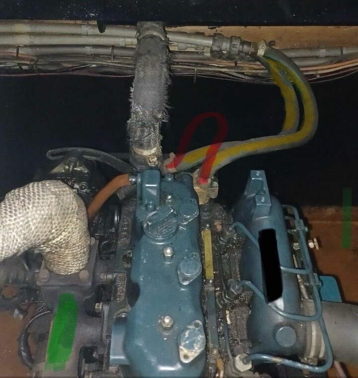
1/ The green is the (dry) exhaust manifold. 2/ The black is the inlet manifold. 3/ The yellow are the hoses to the calorifier coil. 4/ The red is a temporary loop of hose should you need to disconnect the yellow hoses to take the calorifier coil out of circuit for testing. It allows you to run the engine normally, but you'll need a kettle for hot water. A continuous discharge of water from the disconnected yellow hoses, accompanied by the water pump running, is a fair indication that the coil is leaking. You can of course use the redundant coil fed from the eberspacher to effect a repair if needed. Just blank off the leaking coil.
-
Where is all the coolant going?
Eeyore replied to BlueStringPudding's topic in Boat Building & Maintenance
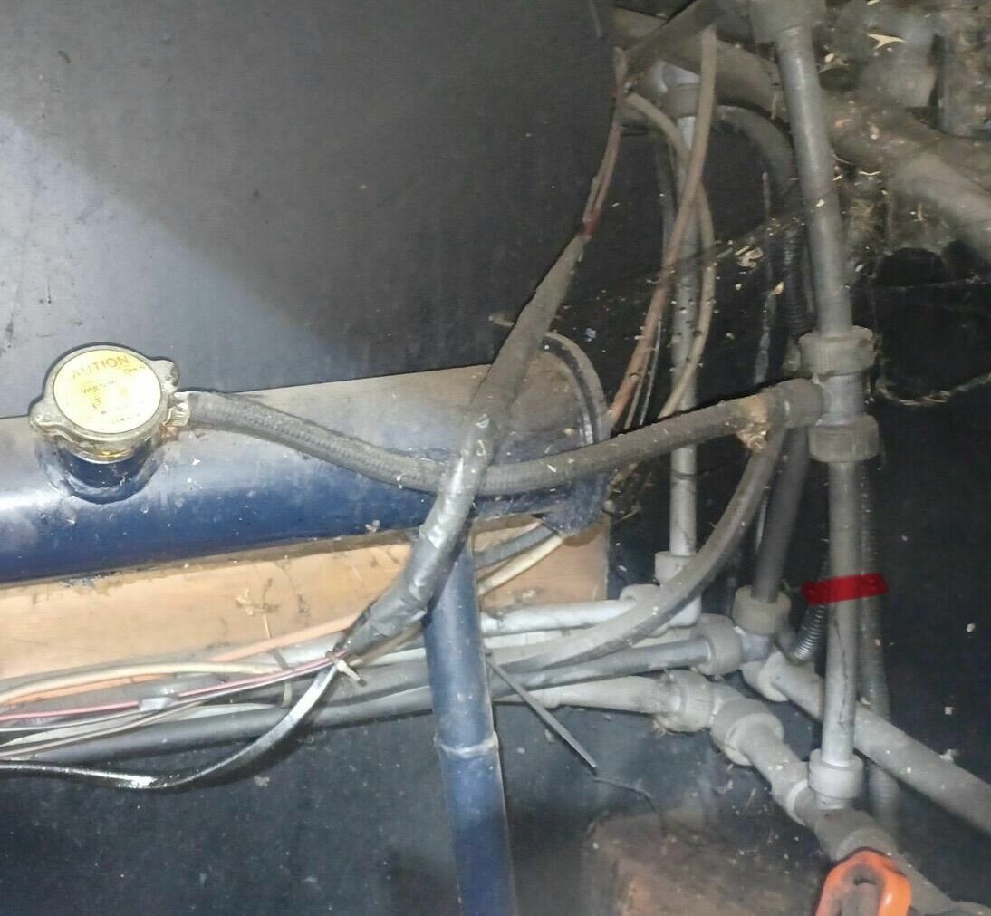
A quick and easy (if a bit messy) way to isolate the two systems. Clean the pipe with a soft damp cloth. Cut the pipe where marked in red, then fit two end stops. This is better/easier/safer bet than trying to dismantle and reuse what could be either mark one or mark two Hep2O fittings. Typical end stop : https://www.screwfix.com/p/jg-speedfit-plastic-push-fit-stop-ends-15mm-2-pack/94176 inserts: https://www.screwfix.com/p/hep2o-smartsleeve-stainless-steel-push-fit-pipe-inserts-15mm-10-pack/3158f cutting tool: https://www.screwfix.com/p/faithfull-3-42mm-manual-plastic-pipe-cutter/587gc All of these bits are often found lurking at the bottom of other boaters "useful drawer", so not necessarily a big outlay.
-
Another vote for light fittings. The electronics in 12volt fluorescents have been regular "performers" over the years, and all were from well known brand/suppliers.
-
Where is all the coolant going?
Eeyore replied to BlueStringPudding's topic in Boat Building & Maintenance
So this is a view from inside the boat looking aft? -
Where is all the coolant going?
Eeyore replied to BlueStringPudding's topic in Boat Building & Maintenance
@BlueStringPudding has a 3 cylinder 1700cc 03 series Kubota marinised by Black Prince, so not particularly "standard", whatever that is! Probably need to check under the floor at the back of the boat; there's often an inspection hatch under the back steps (or nearby). You can also go along the bottoms of the radiators and around the valves with a dry piece of kitchen paper to check for leaks. -
This post cannot be displayed because it is in a forum which requires at least 10 posts to view.
-
Barrus Shanks stop solenoid button/switch?
Eeyore replied to Tasemu's topic in Boat Building & Maintenance
Apologies, I refer you to my earlier Specsaver comment 🙄 -
Barrus Shanks stop solenoid button/switch?
Eeyore replied to Tasemu's topic in Boat Building & Maintenance
Thanks for that Tony, my trip to Specsavers must be overdue. Which is why I've asked for an image of the pump on her engine. I also messaged the OP to make him aware of the request. -
There is precedent for this, some 150 boxes suffered from similar leakage. Quite a difficult diagnosis.
-
Barrus Shanks stop solenoid button/switch?
Eeyore replied to Tasemu's topic in Boat Building & Maintenance
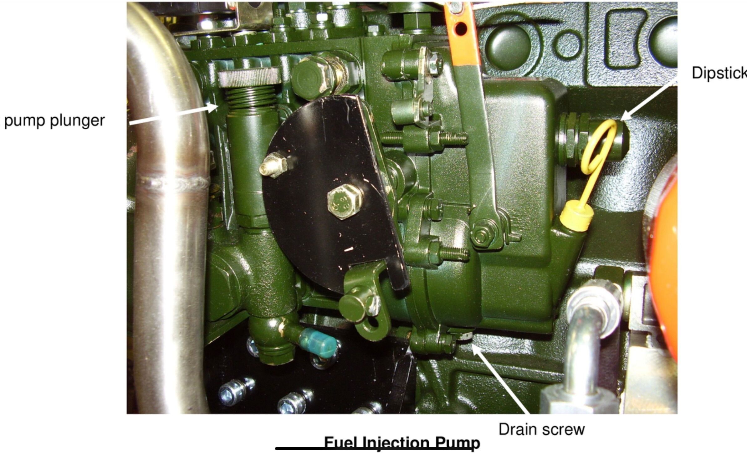
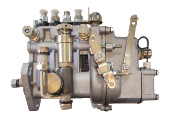
I think there's something else going on here. The solenoid is a pull in type given that the integral "linkage" is a flexible wire that can not be used in a "push" application. The image of the green pump (from Barrus operators manual) seems to show the solenoid energised with the lever to the left; in the run position. The image of the silver pump (from Barrus parts shop) seems to show the lever held in the stop position by a spring hooked around it close to the spindle. Edited to include Tony Brooks observation of the return spring. SO HOW DOES THIS ENGINE RUN WITH THE SOLENOID DISCONNECTED? A similar image of the engine in question would be handy at this point.
-
This post cannot be displayed because it is in a forum which requires at least 10 posts to view.
-
This post cannot be displayed because it is in a forum which requires at least 10 posts to view.
-
Corrosion underneath paint in newly painted bilge
Eeyore replied to MardyBum's topic in Boat Building & Maintenance
Don't fit more than the recommended number of sacrificial anodes; "over protection" can cause coating to lift. -
What does the diagnostic tool say about the circulation pump? Might be worth checking for any significant volt drop issues between the supply and the pump terminals that could indicate a wiring or pump issue. Also worth checking the current being drawn by the pump; most meters can manage up to 10amp when wired into the supply line.
-
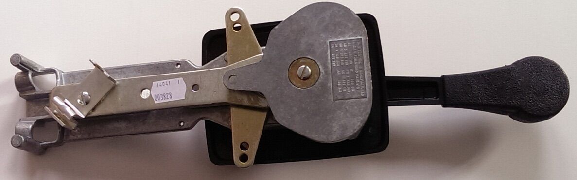
The two arms in the image each have two holes; using the outer holes will give longer cable travel than the inner holes. Yours will probably have a similar arrangement. You can sometimes get away with drilling new outer holes (or extending the arm) to compensate for excess wear, but the controller will likely be well past its best by then.
-
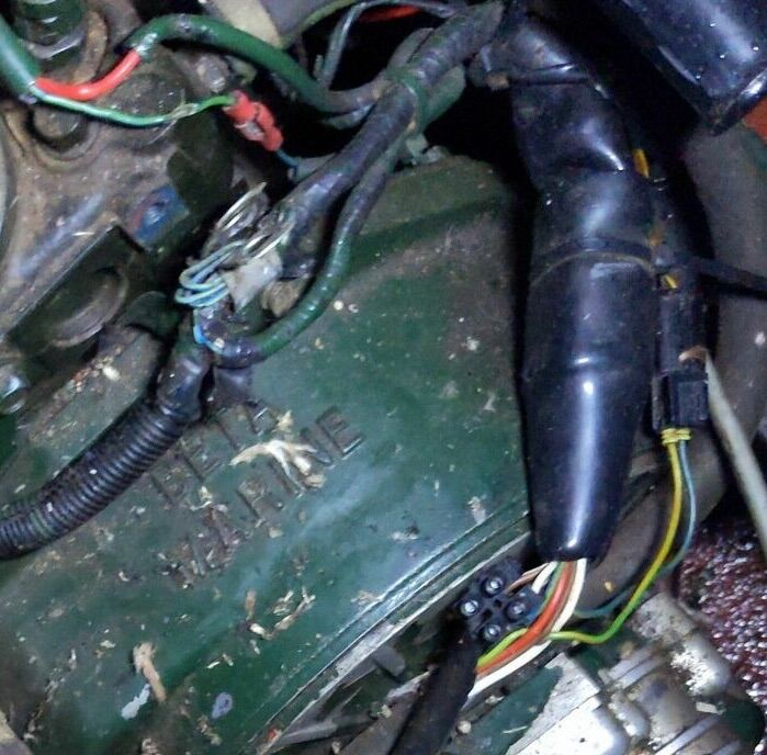
Welcome. As a new owner you may find the following helpful. Always top up with an anti freeze mixture. Anti freeze has a life based on its anti corrosion additives, 2 to 5 years is typical. If your coolant is more like an oxtail soup you probably need to drain, flush and refill. The small green wire, top left appears damaged. A piece of insulating tape will do as an emergency "bodge". The cable clip immediately below the green wire should be attached to the engine, check the wiring for damage first before refitting it. This might also be a grounding point for the harness, others will be more familiar with it. The black plastic item taking up most f the right hand side is the two piece cover for the infamous 11 way connector; well known for a variety of issues. Always worth checking when something odd happens with the electrics. The smaller connector to the right is for wires 12 & 13; usually associated with the second (domestic) alternator. The small black 2 pole "chocolate block" connector right at the bottom is evidence that the main 11 way harness has been altered or repaired in some way.
-
Sterling Alternator to Battery Charger
Eeyore replied to dave921's topic in Boat Building & Maintenance
So are going to tell the boat mover that the boat has a known fault? Offloading a fault for someone else to find certainly isn’t going to go down well. These people (and CRT) have schedules to keep. -
Sterling Alternator to Battery Charger
Eeyore replied to dave921's topic in Boat Building & Maintenance
Not entirely sure that going out with a known fault isn’t the way forward. -
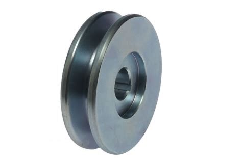
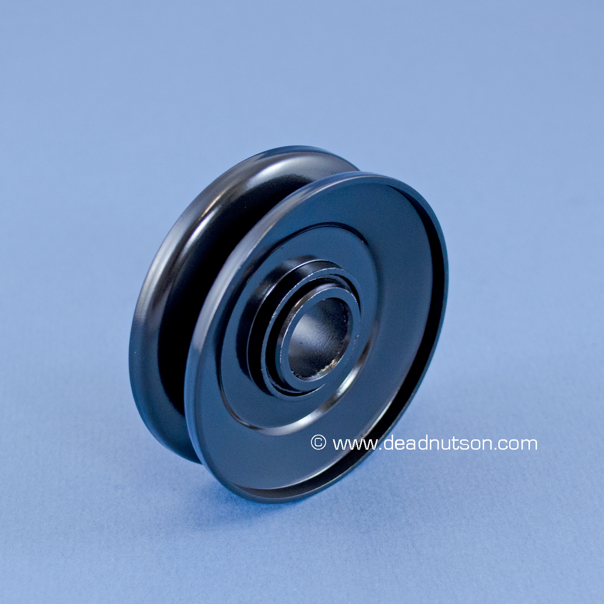
The dark one shows the typical appearance of a pressed pulley. The silver one is turned from solid.
-
Thank you. So using correctly rated minimum length cables with a suitably installed resistor would be almost as cheap and a lot safer?
-
Looking for some technical info here. Are the volt drop and resistance values used for the "long wire" method significantly different to the values found in a typical shunt installation?
-
What @BEego says, plus, an alternator pulley turned from solid rather than the two piece pressed ones. The pressed ones flex a great deal when used with the necessarily high belt tension. This flexing causes the belt to travel radially in the pulley as it traverses the arc of contact. The failure mode was very likely to be related to not re-tensioning the belt after the initial running in period; look for a blue (overheating) mark on the alternator pulley. This would show where the load on the alternator was sufficient to hold it stationary whilst the belt slipped.
-
You type faster than me 😎
-
https://www.facebook.com/marketplace/item/1829339870815308?ref=search&referral_code=null&referral_story_type=post&tracking=browse_serp%3Ae2e70a1f-4485-4575-b349-d362f55cc9c3 Interesting standard of finish, I'm thinking of buying a blunt axe and calling myself a boat fitter. Its certainly news to me that project boats don't need a safety certificate.
-
I belong to various informal groupings that can talk complete bol**ks for hours on end. I’ll see if I can steer one in the direction of lithium 😎