


Steve56
-
Posts
332 -
Joined
-
Last visited
Content Type
Profiles
Forums
Events
Gallery
Blogs
Store
Posts posted by Steve56
-
-
17 minutes ago, Alan de Enfield said:
I thought it was item 55 that is missing ?
Yes thats exactly what I thought.
-
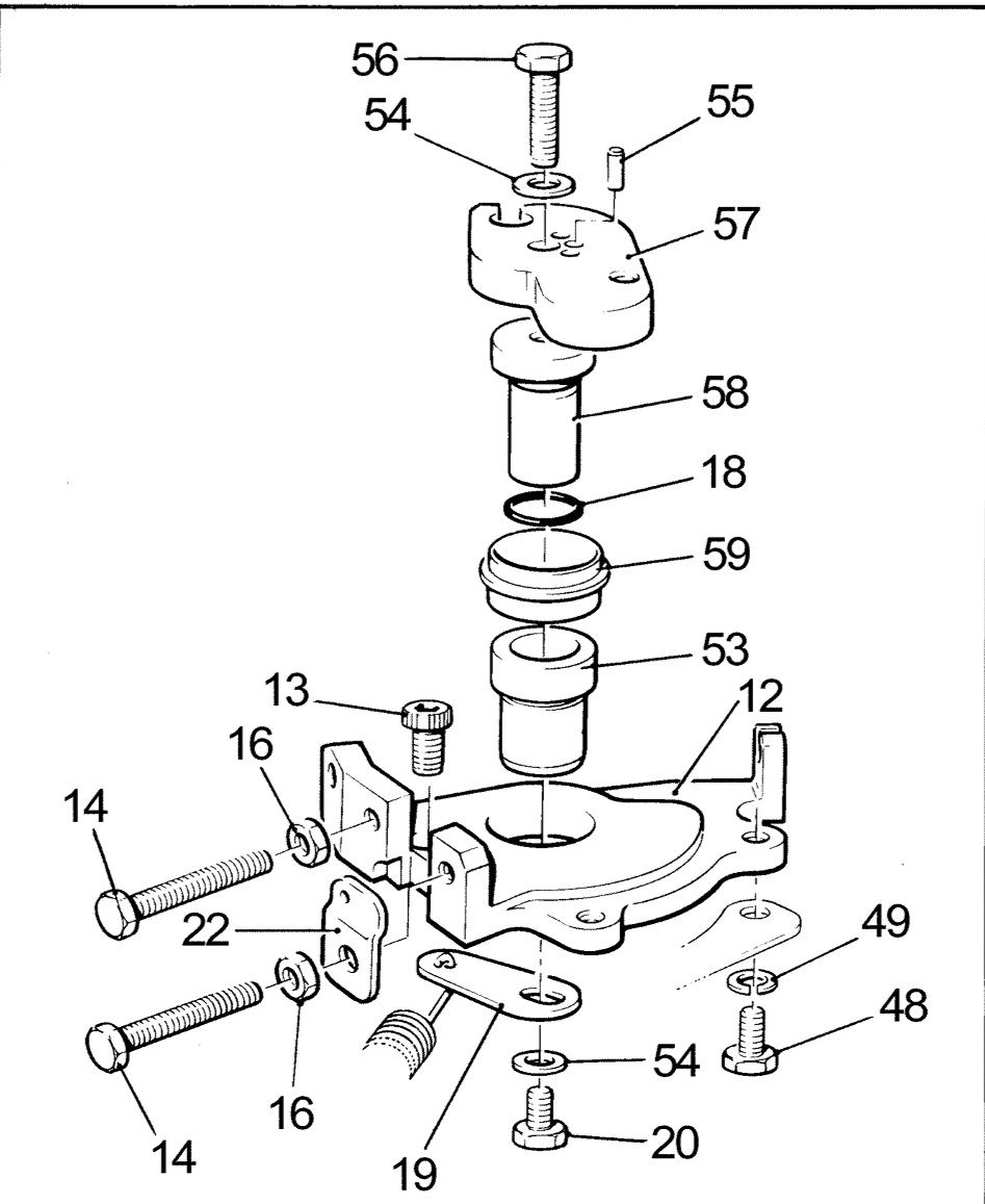
Here is the diagram of how it fits together. I would think that anything you could find that is a reasonable fit into the hole would work. Hopefully if you can stop any movement then the centre bolt will not work loose.

-
Just now, Tony Brooks said:
@Steve56 - would a roll pin ground down for length do the job?
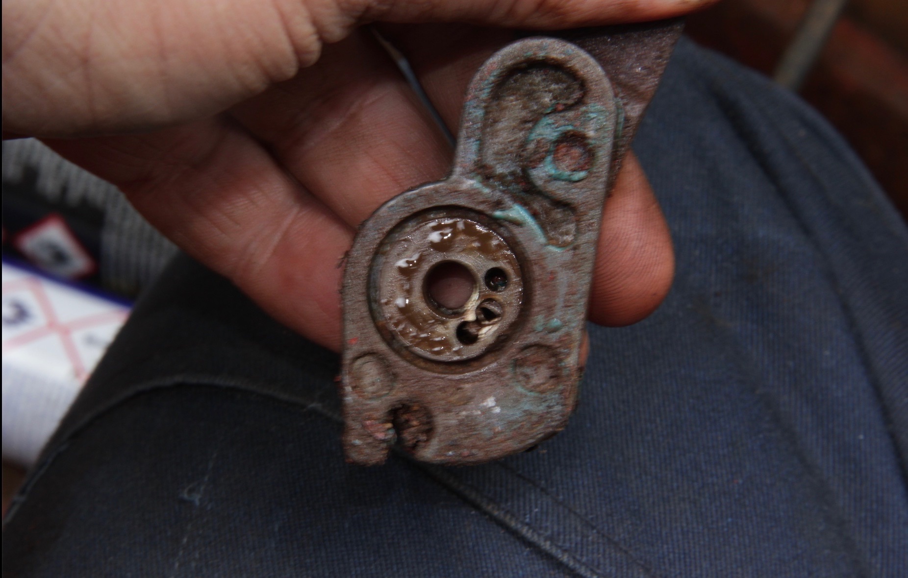
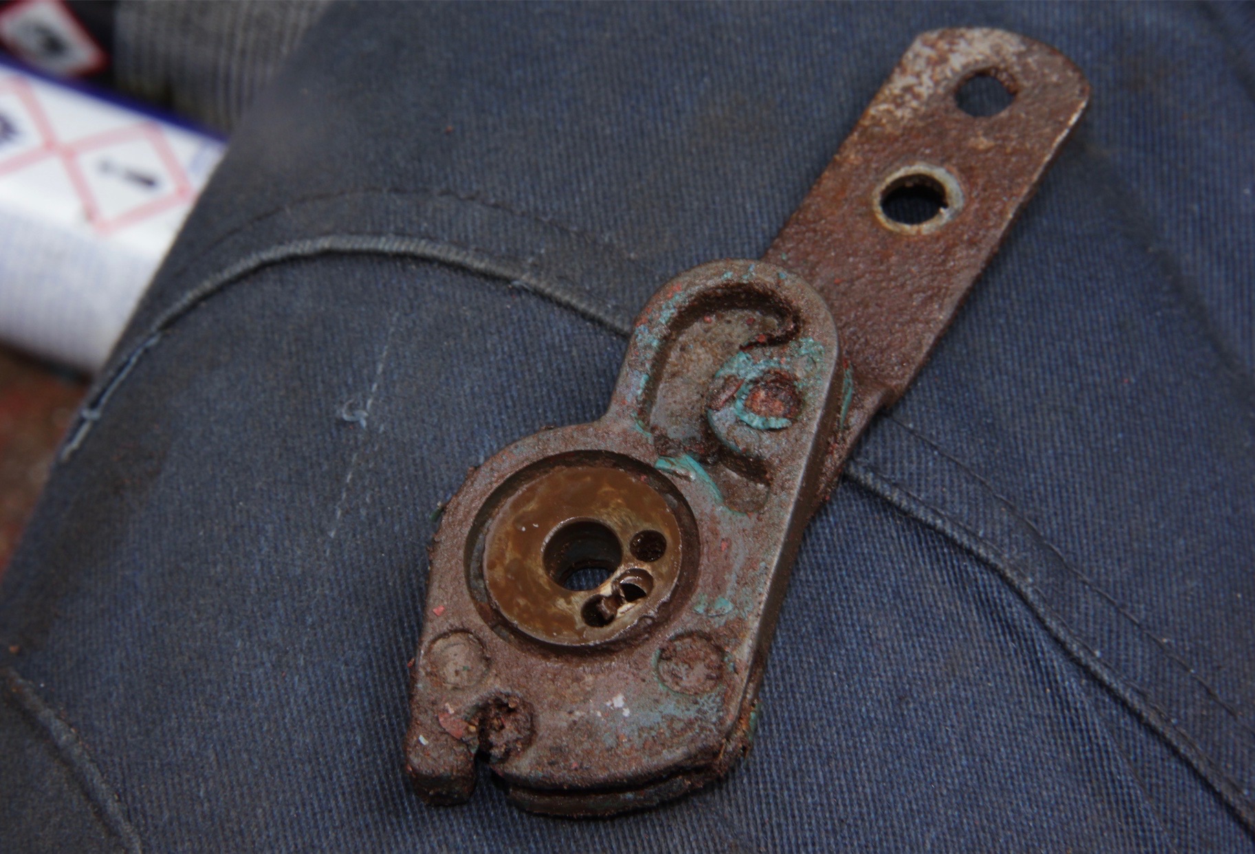
Yes I would have thought that would be fine. The only problem I can see is that the holes in the lever appear worn. There should be 3 distinct holes, but I looks as though 2 of them have broken through.
3 minutes ago, pluto83 said:have you got any images to show how it should look please
I will have a look. But probably be tomorrow now.
-
Just now, Alan de Enfield said:
I have two 'master parts manuals' :
One is "Issue 9 Jan 1999" and the other "Issue 11 May 2001"
What issue do you have ?
I checked this in my technical bulletins. They list all the mods for all the models. Its what Lister R&D department used to issue to us service engineers among others.
-
 1
1
-
-
As a follow on if its any help, I have just checked through the technical bulletins and the pin part no is 027-10103
-
2 minutes ago, pluto83 said:
unfortunately tightening the bolt done nothing, so ive disconnected it and appears there should be a pin. mating the two marts together but I still cant find the part number in the master parts manual.

You are quite right and that lever should have a locating pin fitted. I think it is a case of which parts manual you are using. The lever you have there is a later modification so if your manual is from an earlier date it won't be shown.
-
1 minute ago, Tony Brooks said:
That wll explain the other grey pipe in Brian's photo that I can't see its termination. Should be a simple installation.
Thats the one. If you look carefully at the photo you can just see the other pipe. If you look you can just see the two 90 degree elbows, which are flow and return.
-
Beta and Nanni both fit the caloririer in different ways. On the Nanni engine they just seem to cut the water pump bypass hose and use this as the flow and return to the calorifier. On the Beta they would normally take the hot water from the rear of the cylinder head and the return would tee into the engine return from the skin tank. This take off from the rear of the head would have a restrictor fitted so as not to still ensure good engine circulation.
-
Possibly a small amount of air entering the fuel system. Or maybe a little stiffness on the fuel pump rack.
-
1 hour ago, Tony Brooks said:
I think Bods is fixated on those marks because he does not understand what they are for. In my view if he has not had the pumps out of the engine they will be correct so can be ignored. He does not seem to grasp that.
I think you are right . It does sound to me as if the marks are correct. I think they should just be left alone.
-
There seems to be a lot of talking at cross purposes. Firstly the position of the line on the fuel pumps determines how much fuel the engine can use at full speed and has nothing to do with idle speed. To set the lines on the pump(g setting) you would use the correct size feeler under the stop lever, loosen the small bolt on the back plate and rotate until line on the rack aligns with edge of pump. Therefore when the feeler is removed the line will disappear inside the pump, so what you have is correct.
Now the small spring you have on the rear pump is the idle spring and if you undo the lock nut you can turn the collar to adjust the tension which alters the idle speed. To adjust correctly you would totally slacken the idle screw on the speed control lever. You would then tension the idle spring to give a speed of approx 800 rpm and lock in this position. Then using the idle screw on the speed control lever increase the speed to around 850 rpm (recommended idle speed for this engine). That is about it.
-
2 minutes ago, BODs SR2 said:
Ill sort it tomorrow off out for a run. Thanks for your interest. Is it best to PM.
OK thats fine. Probably best to post here as it my be of interest to others. Unless of course I am told anything different.
-
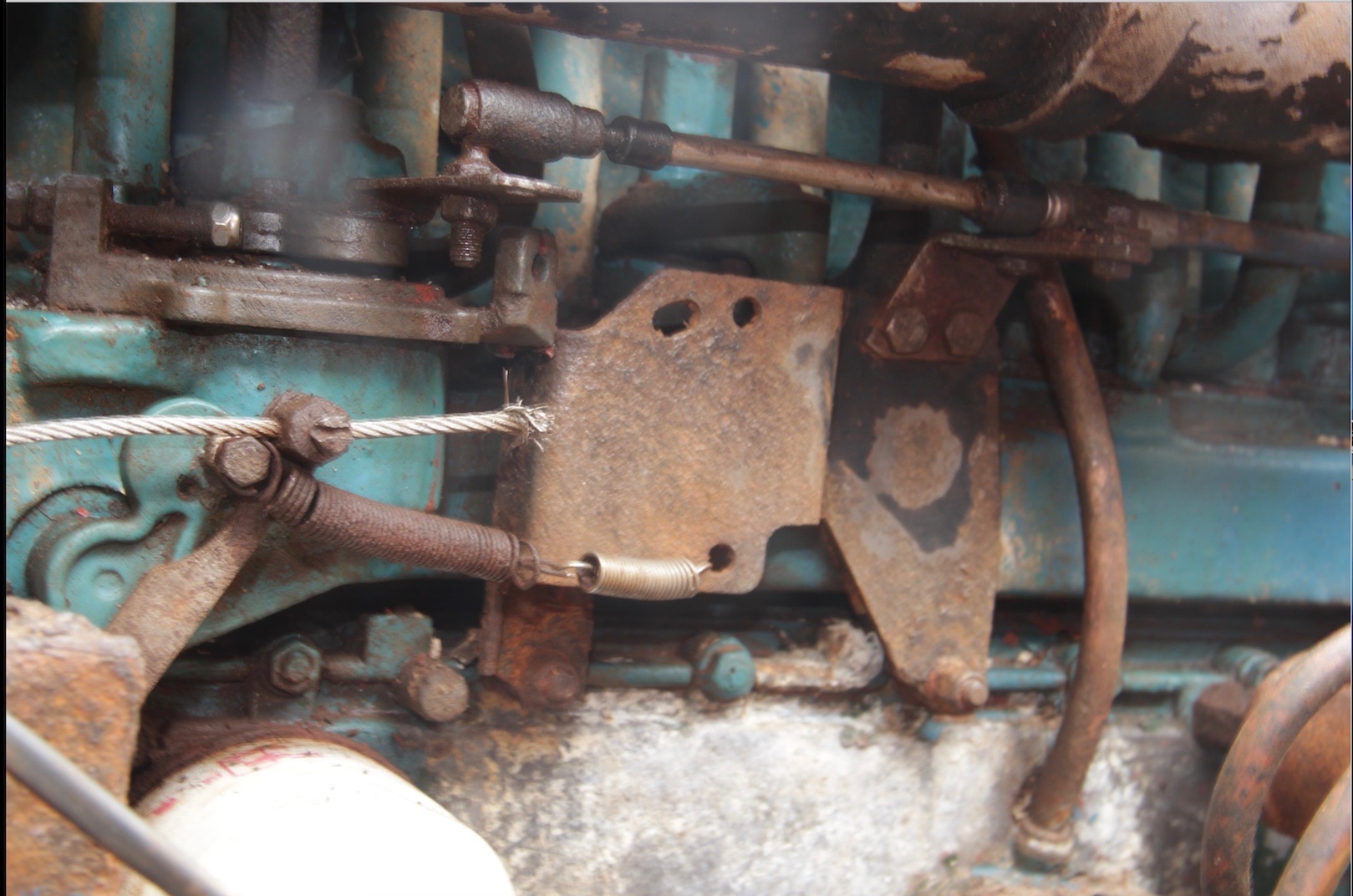
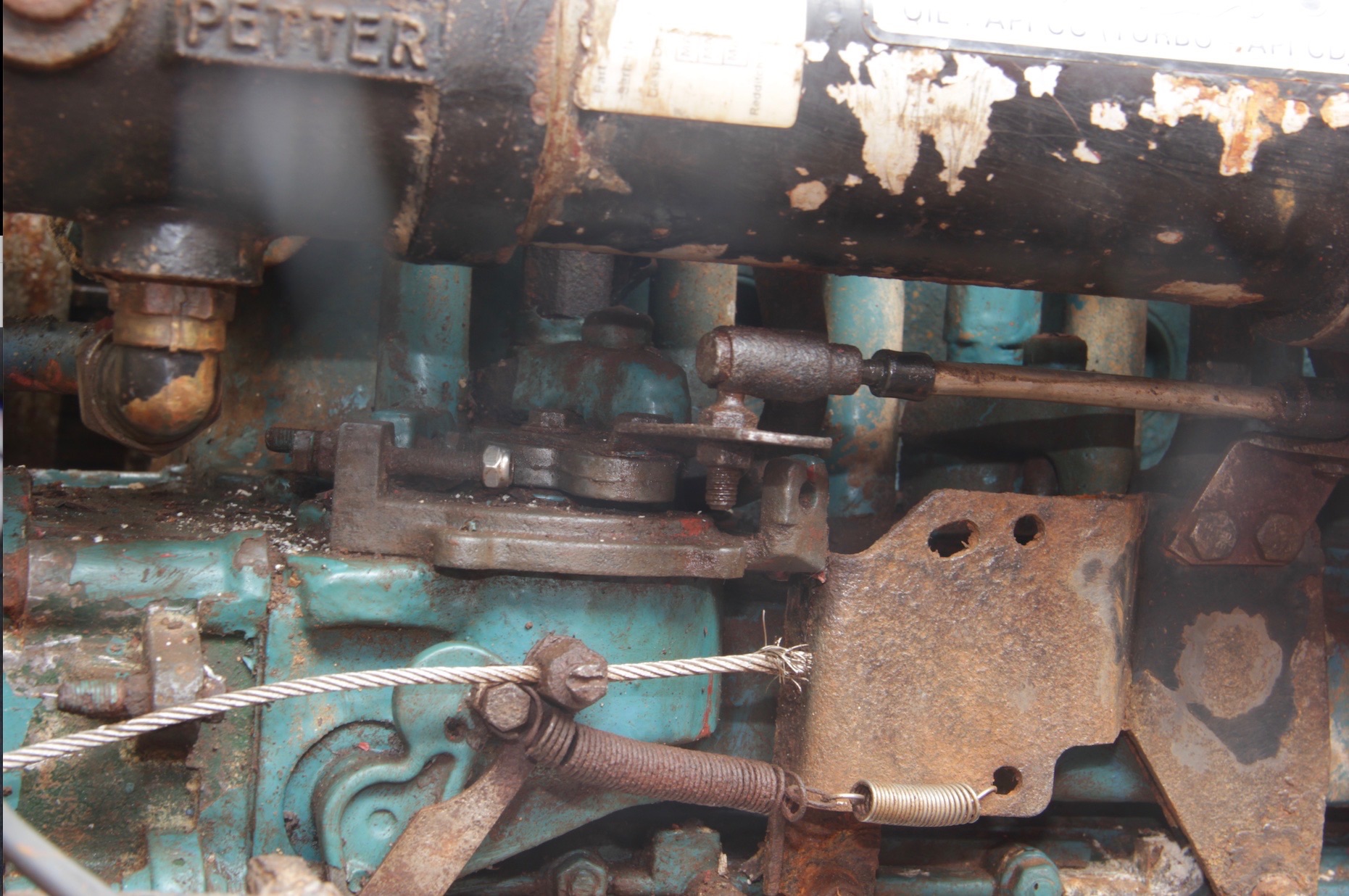
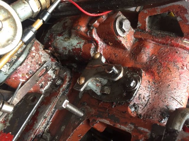
9 minutes ago, BODs SR2 said:
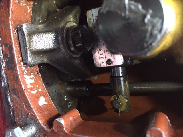
Image 1 & 2 shows the start/stop handle and all the linkeage shown in the manual for it seems to be enclosed in impenetrable casing. The only idloe adjustment I can seem to get to is the adjuster screw on image 3. I need to try and adjust it though because the setting marks on the pump linkage should be visible next to the pump body but they are hiding behind it a couple of mm.
As I said in the earlier post I need to see the complete flywheel end injection pump showing the whole linkage. The photo you posted only showed half of the pump.
-
1 minute ago, Tony Brooks said:
FWIW all our SL4s had them and they were mated to LH150 boxes so were bought as marine units.
I think by the time Listers were doing the SR engines they were not used.
-
1 hour ago, Tony Brooks said:
I am not so sure because I think all the S series had an option for self bleeding and if so the leak off pipe has spurs that drop down through the push rod chest and connect to the injector pump bleed screws. If you take the rocker covers off and there are no pipes that disappear down into the depths of the engine then I agree with Steve but would add that I would get new rubber bushes if they are not supplied with the new pipe.
Personally I would take it off, anneal it and then take it to an old school car body shop or garage with brazing kit and get it silver soldered unless it's the injector connection that has failed. I reckon a bit of folding money would sort it. In that case I would smear the rubber bushes with non-setting jointing compound like Hylomar.
As Tony Brooks said check for pipes going down to the pumps. I did forget to mention this. Although to be honest I think these were used more on industrial engines. Very rare on a marine unit.
4 minutes ago, BODs SR2 said:Genuinely cant find it all ref photo of the flywheel end. Nothing remotely resembling it there.
We need to see the other side of the pump in the photo.
-
There are no washers where the leak off rail fits into the injector. Just undo the nuts and remove. It may be necessary to remove the injector clamps to allow the pipe to be lifted out. Basically should be ab easy straight forward job.
-
14 hours ago, r-harris said:
BTW Does anyone have a handle on adjusting the idle speed re. p36/7 of the manual ie. where physically is the assembly marked A-G on p36. How can I access it???
Items shown are the components and adjustment of th idle spring. This is found behind the fuel pump housing door fitted on the fuel pump rack on the rear most pump. Basically you would set this so the engine runs a little slower than the recomended idle speed. Then on the speed control lever increase the speed to the recomended idle.
-
Post a picture of what your looking at and may be able to advise.
-
3 hours ago, r-harris said:
Sounds logical to me. Ill pay a bit more and leave it firmly in place.
Regards to you all.
After a quick look at ebay it seems some have the threaded fitting forward and some have the fitting to the rear of the engine. It seems like a lot of these parts are some sort of copy. To my knowledge all genuine Lister SR leak off rails would have the thread at the forward end.
-
As Tony Brooks has said the reason for the pipe is to allow any air trapped in the fuel filter to return to the tank. The engine will work without but could cause you problems if any air is present. Lister would always fit this pipe on engines fitted with a fuel lift pump. On gravity fed engines it was not fitted.
-
There is no drain plug in the adaptor. Any water around the fan will not cause any problems, it will just get blown out. When these were used as lifeboat engines one of the tests was to run engine sat in water up to the crankshaft level. Engine would run well and just blow the water from the air duct.
-
-
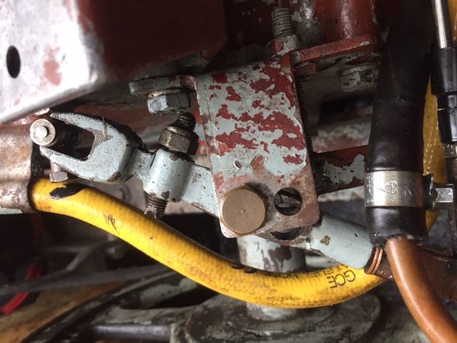
In image no 1 the hole should just be blanked off. I think this may have been done with a small core plug rather than a bolt. Check to see if there is a thread in the hole. If there is you can use a bolt but ensure it is as short as possible so as ot to foul anything internally.
-
lpws4 go into gear but no revs
in Boat Building & Maintenance
Posted
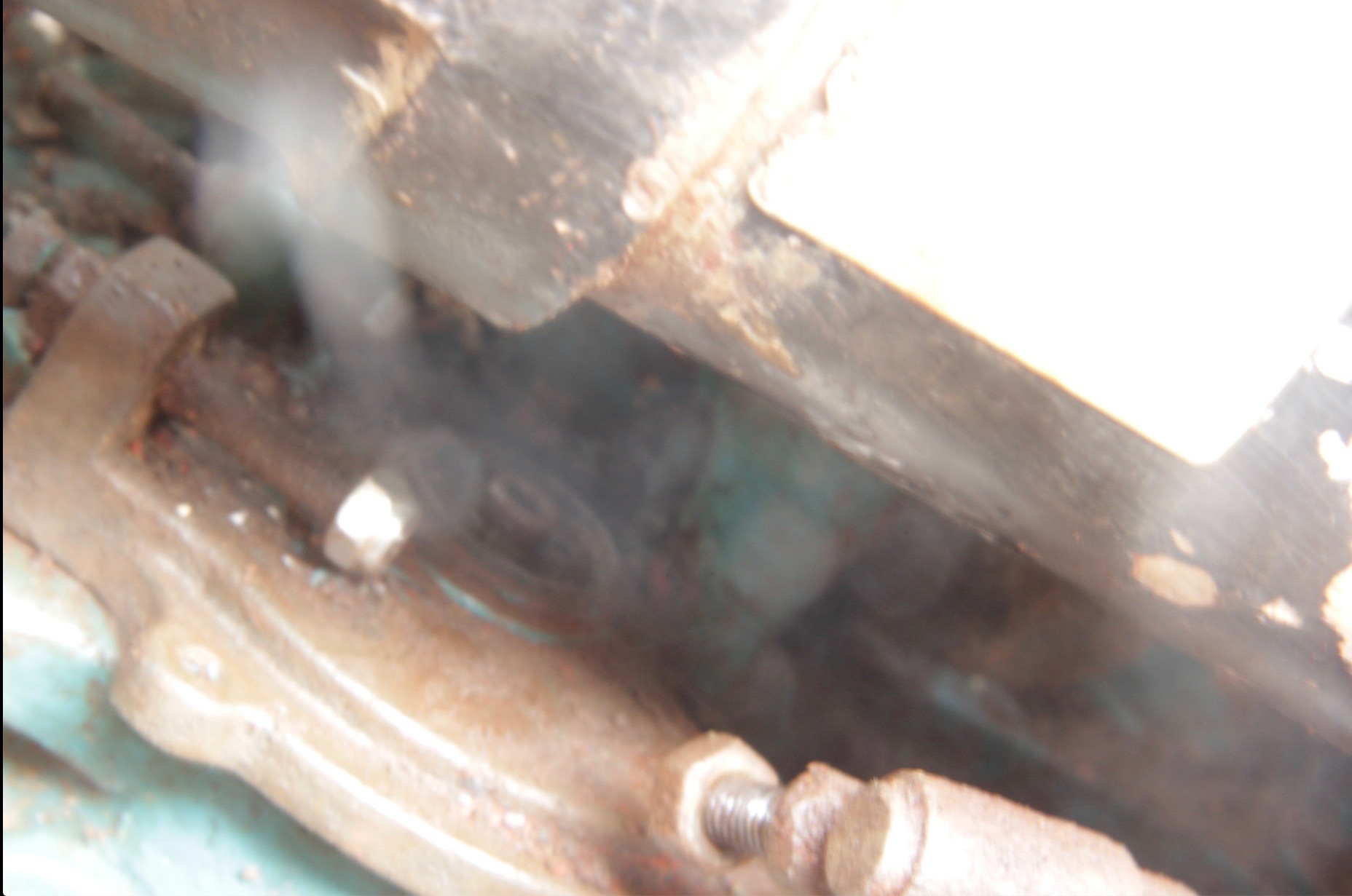
If the engine has been running for some time with the centre bolt loose the maybe the pin sheared off.