


Steve56
-
Posts
332 -
Joined
-
Last visited
Content Type
Profiles
Forums
Events
Gallery
Blogs
Store
Posts posted by Steve56
-
-
5 minutes ago, Stilllearning said:
A diagnostic trick I have used is as follows: with the engine ticking over, from a steady place, put one foot gently on the top of the engine. If the noise stops, it’s probably the mounts that are shot.
The alternative is to use the old long screwdriver/steel rod stethoscope method, it’s good for annoying engine noises.
That's always a good test. Just stand on each corner and listen what happens. Or you could use a bar under each engine Bearer in turn which will give the same result. Either way a good test.
-
 1
1
-
-
1 hour ago, NewCanalBoy said:
Ah - I haven't got any of these ?
What actually happened was that I had that tapping noise, like others i thought I had some problem and more than one mechanic suggested my drive plate was chattering away, until I took up some drive and then it disappeared completely, only for it to return when back in idle.
I took it to a mechanic and when I demonstrated what was happening he agreed and ordered a new driveplate.
When I went to get it changed he took the old driveplate out and said it was perfect but - 'You've got two broken engine mounts'
As I was booked in for that day and couldn't get any new engine mounts quickly he had to improvise. He had a threaded bar which he cut down into smaller sections and then installed into the mounts. I didn't see him do this but he must have just used a bit on the underside to hold it in place ?
Basically it was concluded that I need meatier engine mounts, or raise up the ones that I have as there is space between the top of the engine mount and the engine feet.
That sounds a little concerning. Is this bit of threaded bar the correct hardness or just an odd piece of mild steel studding he happened to have. If the latter it probably won't last long. Is he saying that the engine is mounted to far up the stud. If so this could cause problems. If that is the case then the mounts would require packing below them. Why is he talking meatier mounts. If the engine is to far up the stud then meatier mounts will make no difference. Engine mounts are selected by engine weight. If the mounts are original to the engine then the engine manufacturer would have done a lot of tests to ensure they are correct. Maybe a bit more info or a few photos would help.
-
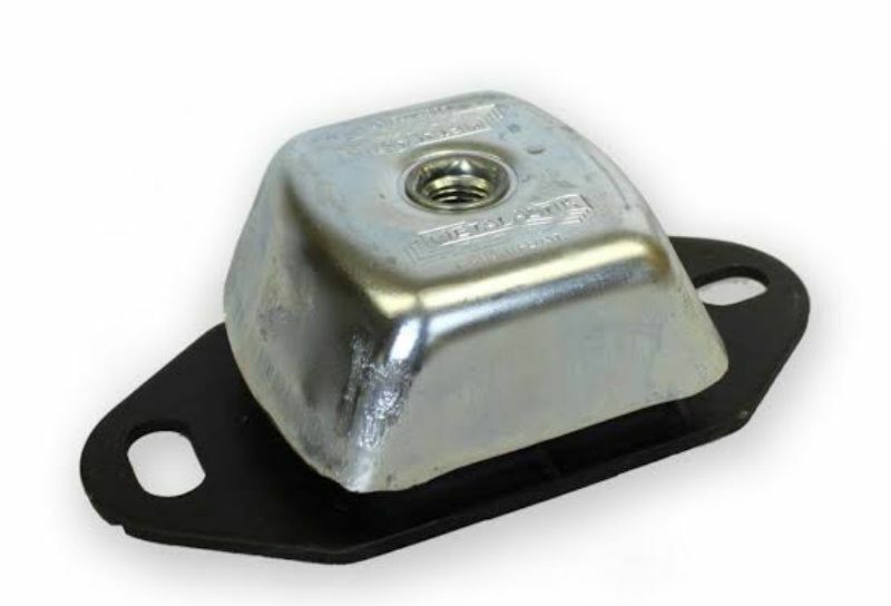
Here is a photo of this type of mount. The stud is a totally separate part which may or may not be used dependent on application. If used with the stud then this is just screwed in and locked into position with the thin locknut. The only thing to watch out for is the stud itself. There have been various versions of this mount. Some use a shouldered stud which is fine, just screw in until the shoulder buts up to the top of the mount and tighten locknut. Also you come across this same style of mount that uses a parallel stud. With this type you need to be a little more careful because you determine the stud position and then lock in place. I have come across a number of cases where the stud had been screwed in to far before locking in position. This results in the lower end of the stud tapping/knocking on the engine bearers while engine is running.

-
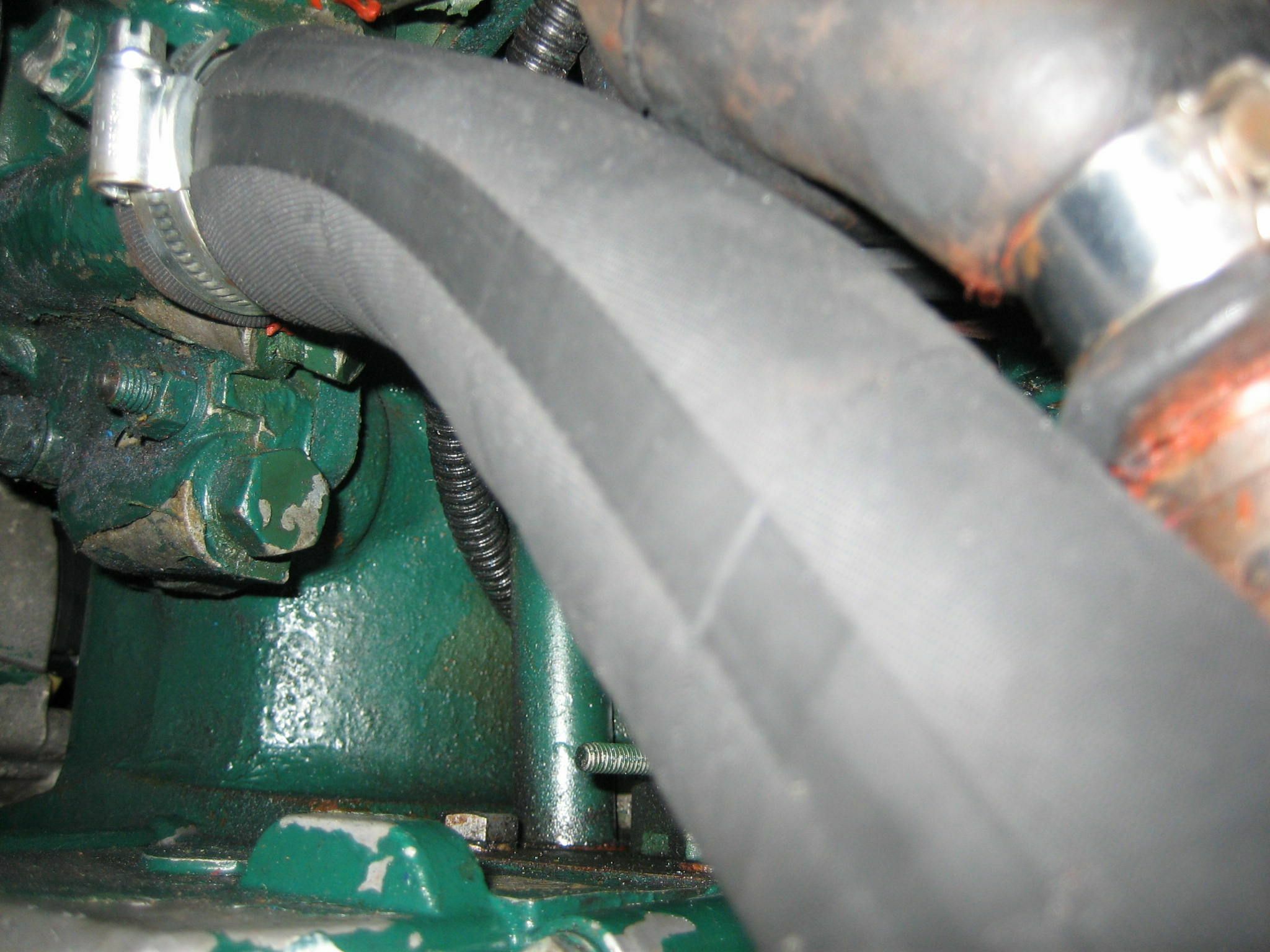
Not saying its the right or wrong way but if I was doing the job I wouldn't attach anything to the housing. Personally I would make some sort of support rail and attach to engine beds. Then all pipework could be clipped to this.
-
6 hours ago, john6767 said:
It has been 8 to 7 in the summer for years, I am less concerned by closing the bridges an hour earlier, than with the closing a day a week. I guess with planning the half the canal every other day could work, but not impressed at all with this.
As you say it has been 8 to 7 for many years. I also remember the time when it was open 7 days a week winter and summer. But going back many years in the old BW days, and at a time when they were so say short of money they did a similar exercise. After discussions with the boaters forum that was running at the time it was agreed to have the 2 day winter closing as a temporary measure. This was to last a year or two and then back to normal. I think we all know how that ended up. All I would say is be very careful, I think once implemented it will not go back.
As for the staggering amounts of money that has been spent, so say making the bridges suitable for boater operation. The trouble is they just won't let the boaters use them. Patch bridge was done for this purpose. It is ready to go. Just need your BW key to operate the consul. But CRT will not let this happen. When there is no bridge keeper the power is turned off and a padlock fitted to the bridge. In fact nearly every bridge with the big silver consul outside the bridge hut could be operated by a boater. The odd one out is Sandfield bridge which was going to be operated with a phone app, but they could never get it to work safely. There have been many cases cases where it has either stuck open or closed. Or the barriers have come down with a person or car stuck on the bridge unable to get off.
But good old CRT, all they want to do is give us all a massive price hike and cut the services at the same time.
-
7 minutes ago, bizzard said:
And some have a 12v heater element in the induction air intake to aid cold weather hand starting with the decompression levers.
To be fair never seen a heater element in the inlet manifold of an ST engine. Also if the engine is a hand start engine it seems unlikely that 12 volt would be available. But in saying that I could be wrong.
-
19 minutes ago, knares said:
thanks guys, all my questions answered, now i need to look some where else
the cold start is interesting
All the cold start does is allow the pumps to open up a little more and deliver more fuel. Also some of these engines have plastic cups on top of the ducting and screwed into the inlet manifold. This is another cold starting device. It allows you to inject oil on top of the piston which raises the compression and aids cold starting.
-
1 hour ago, Marko J said:
I don't know, this is rear section

It would be my guess that the third greaser is to lubricate the rear shaft bearing. I have come across on a number of older Dutch Barges. As I say it is only a guess as the photos don't show enough info.
-
1 hour ago, john.k said:
Dont you get extra fuel for a cold start by pulling out the stopper?.........I know you can pull out something for excess fuel..........not that I need it in the blazing heat.
Yes that is correct. Pull the stop lever out and let it rotate in an anti clock rotation. This allows the pumps to open up and deliver more fuel to aid cold starting. It is important that the stop lever is returned to its normal position immediately after start up.
-
10 hours ago, knares said:
ok guys
this is what i have got
dose it look normal, or is some thing missing
the wire is the stop cable
No it doesn't look normal if your engine is a variable speed model. There appears to be very little movement on the speed control lever. I would only expect to see something like this if it was a fixed speed engine.
-
8 hours ago, Peugeot 106 said:
There's mine before I put sender in
Personally I wouldn't use that fitting for a temperature sender. That position is for cool water return to the pump so therefore will not give an accurate temperature reading. You could overheat your engine well before any alarm is given.
-
5 minutes ago, Eeyore said:
The sender/switch and the blanking plug (the one partially obscured by the fuel pipe in the photo) have what appears to be sealing washers under the hexagonal head. This would suggest that the threads are a parallel type, needing a washer achieve a seal. I’m not convinced that the blanking plug is original, perhaps @Steve56 could comment please.
If I remember correctly there are a couple of tappings in the water pump. The smaller one is 1/8 BSP and the larger one is 3/8 BSP. On the photo the calorifier take off union is fitted to the larger hole. The switch that is screwed into it is 1/8 BSP, but with a parallel thread. Therefore will have a copper washer fitted.
-
1
-
-
2 minutes ago, Tony Brooks said:
Not answering for Steve, but my first question would be was the block face(s) checked for truth, and do these Listers need liner protrusions. I can't see a proper head skim causing that sort of record. Thne we are into do these Lister use stretch head bolts/studs.
I would agree that the block face should be checked. These engines are not fitted with liners so no issue there. I agree that I can't see any issues with skimming the head. These engine used stretch bolts to hold the head in place. Lister always said they could only be used twice and then should be replaced. I suppose the other thing to take into account is the head gasket. The original Lister gaskets had a sealant on the faces of the gasket. If people are using copies, how good are they.
-
22 hours ago, Psychalist said:
Oil filters is going a bit off topic. The three cylinder uses a wider, but not longer can, but most equivalents come in as the narrower can - meaning they're not really equivalent - caveat emptor and all that. The difference seems only to be volume and all have the same bypass. I have used the smaller can and not noticed any difference. Getting to around 100 hours the oil seems to get darker more quickly. Maybe the filter is becoming blocked at that stage. I've not had a problem with the lifters. I had a Cavalier that used to get hydraulic lock at high revs and would wear through hardening on the camshaft. I had three replacement camshafts in that car.
Interesting the two cylinder seems to have the relays hanging down the side of the engine where moisture, dirt and oil can get in the connections.
Mine (1997 vintage) has them enclosed in a box:
Despite that, as Tony said, probably an over complication and another source of problems. E.g. Fuel cut-off solenoid jamming due to incorrect alignment, going over-current and tripping. A pull cable is simpler and easier to diagnose.
As for the cylinder head having a lip....none here:
The earlier engines had all relays mounted to the engine. As the vibration from the engine used to cause the relays to fai prematurely Lister came up with the remote mounted relay box on the later engines.
As for the fuel shut off solenoid, if anything caused it to jam or stopped it from reaching its full travel then the circuit breaker would trip on over current.
Interesting how we have got to this point from the original question about control panels.
-
1
-
-
10 hours ago, Tony Brooks said:
It is almost certainly an unnecessary hang over from automotive origins. The reduced power to the glow plugs for a period once the engine has started is intended to reduce diesel knock and probably emissions from a cold engine, Again, an unnecessary complication for boat use (on a pre RCD boat). Many boats do not have a relay to power the glow plugs but it is a good idea to use a heavy duty one down close to the engine to power the plugs. This saves the full glow plug current passing through the ignition switch.
As you say these controllers were not really needed. They were fitted so that the heaters would work automatically when the ignition was switched on. Can't see the point myself as there is no hardship in holding a key in a heat position. A simple relay in the heater circuit will do the job.
-
13 hours ago, Tony Brooks said:
But is it the one for the short-lived panel using LEDs and electronics, which is the subject of this topic? You will find that bar different drawing conventions, all makers diagrams are virtually identical.
That is an engine wiring diagram for a much later engine. Also I very much doubt the engine in question has an insulated earth system. The one helpful thing is that Listers tended to be pretty constant on there colour codes. Therefore if you look at any diagram and see what each colour cable does it should be the same no matter what age of engine.
-
4 minutes ago, pt2583 said:
It would be beyond me with out diagram, I was looking at this option
https://www.dragonmarinesystems.co.uk/store/p124/Basic_Lister_Marine_Basic_replacement_panel.html
Yes that's the sort of thing you could probably use. Very similar to the ones I was using. Seems a little expensive for a keyswich and a few lights. But it is a tidy job and hopefully not to difficult to connect. I would assume you would get a connection diagram with it.
-
11 minutes ago, pt2583 said:
Do you make the panel your self or purchase from somewhere
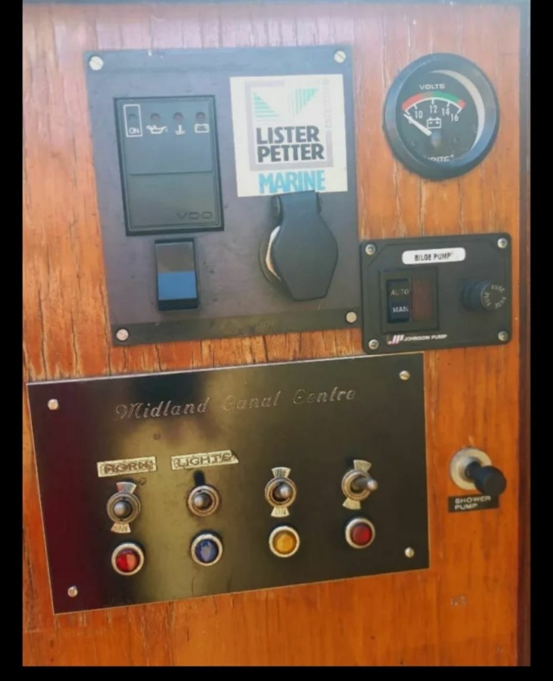
As I was employed by Lister I bought about 20 of the old ST panels out of a skip. They were the old silver panels with a keyswich and 3 warning lights. But in saying that it would be an easy job to buy the parts and make your own.
-
16 hours ago, pt2583 said:
Don't like to be the bearer of bad news but that panel was only supplied by Lister for a short while. All the lights and various other electronics were housed in a sealed box. They were never much good and I'm surprised you have one that's lasted this long. That's why Lister only supplied for a short time. Personally I wouldn't trust anything the panel is displaying. I've changed a number of these over the years and replaced with a simple hard wired panel.
-
15 hours ago, BEngo said:
RW Davis were into the K's and J's but are now running off that part of the business.
Phil at RW Davis had a few of the bigger engines hanging about. So certainly worth a call.
-
If my memory serves me I think that they were a made of a card type gasket material a couple of mm thick. Mind you I don't think it make to much difference whatever you use.
-
8 hours ago, Tony Brooks said:
So unless it is oil down the valve guides or up past the pistons then the oil leaking past the head gasket is another highly questionable statement.
It would certainly seem that way. On the Alpha range of engines the oil feed to the rockers is up through the centre of the hollow push rods, then draining back down the pushrod tubes themselves. With tubes being totally independent of the head gasket.
-
One thing to bear in mind when talking about oilways and head gaskets on the Alpha engines is that there are no oil ways in the block or head.
-
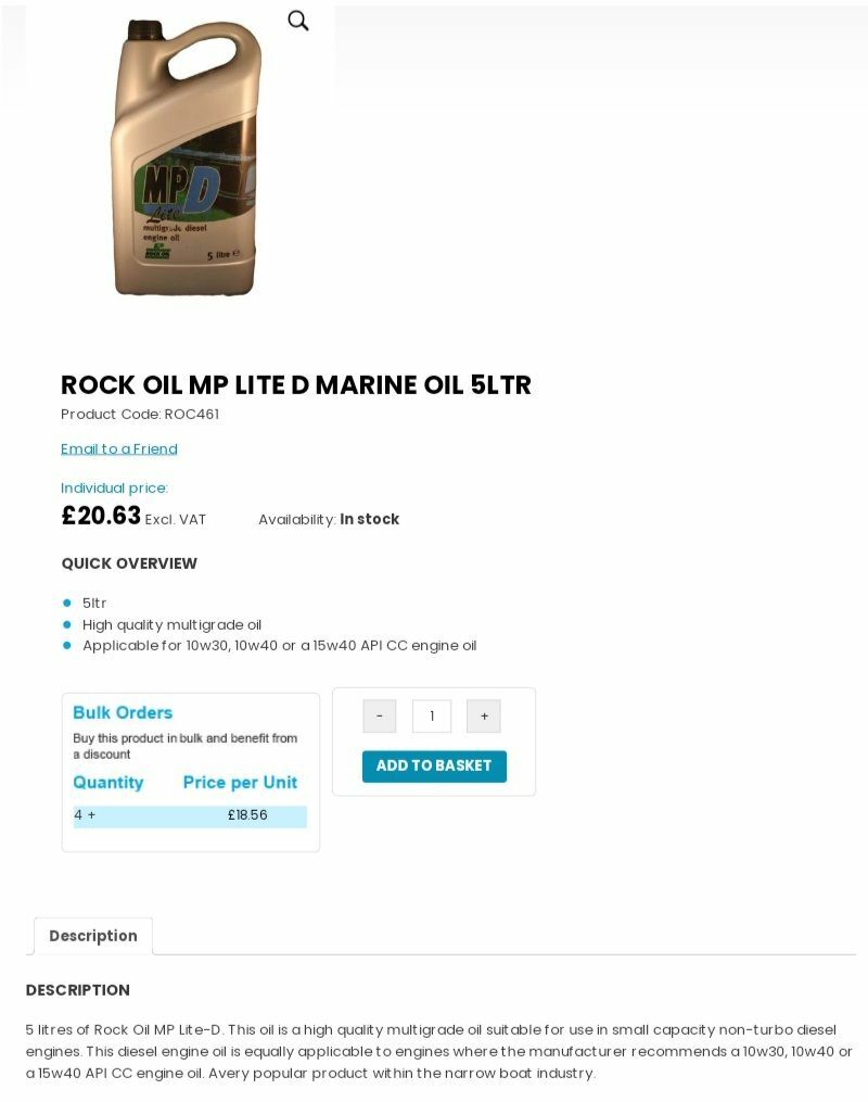
It always seems to get a good debate going when oils are mentioned. If I was running an Alpha engine (except the turbo model) in a boat this is the oil I would be using.


Engine Mount ......
in Boat Building & Maintenance
Posted
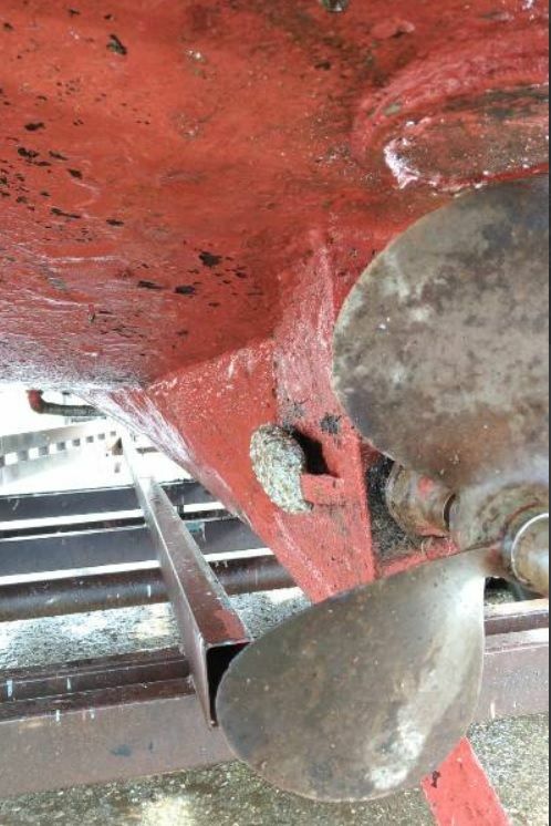
I would agree that the engine is mounted a little high on the stud. Ideally you should aim for around 5-10 mm of stud showing. You could probably put around 15 mm packers under the mount which would certainly help.
Also looking at the way the rubber is being pushed out from around the mount it looks as if its seen better days.