Spoonman
-
Posts
29 -
Joined
-
Last visited
Spoonman's Achievements
")
Engager (3/12)
0
Reputation
-
 Spoonman changed their profile photo
 -
Ignition system wiring for a127 / Lister sr2
Spoonman replied to Spoonman's topic in Boat Building & Maintenance
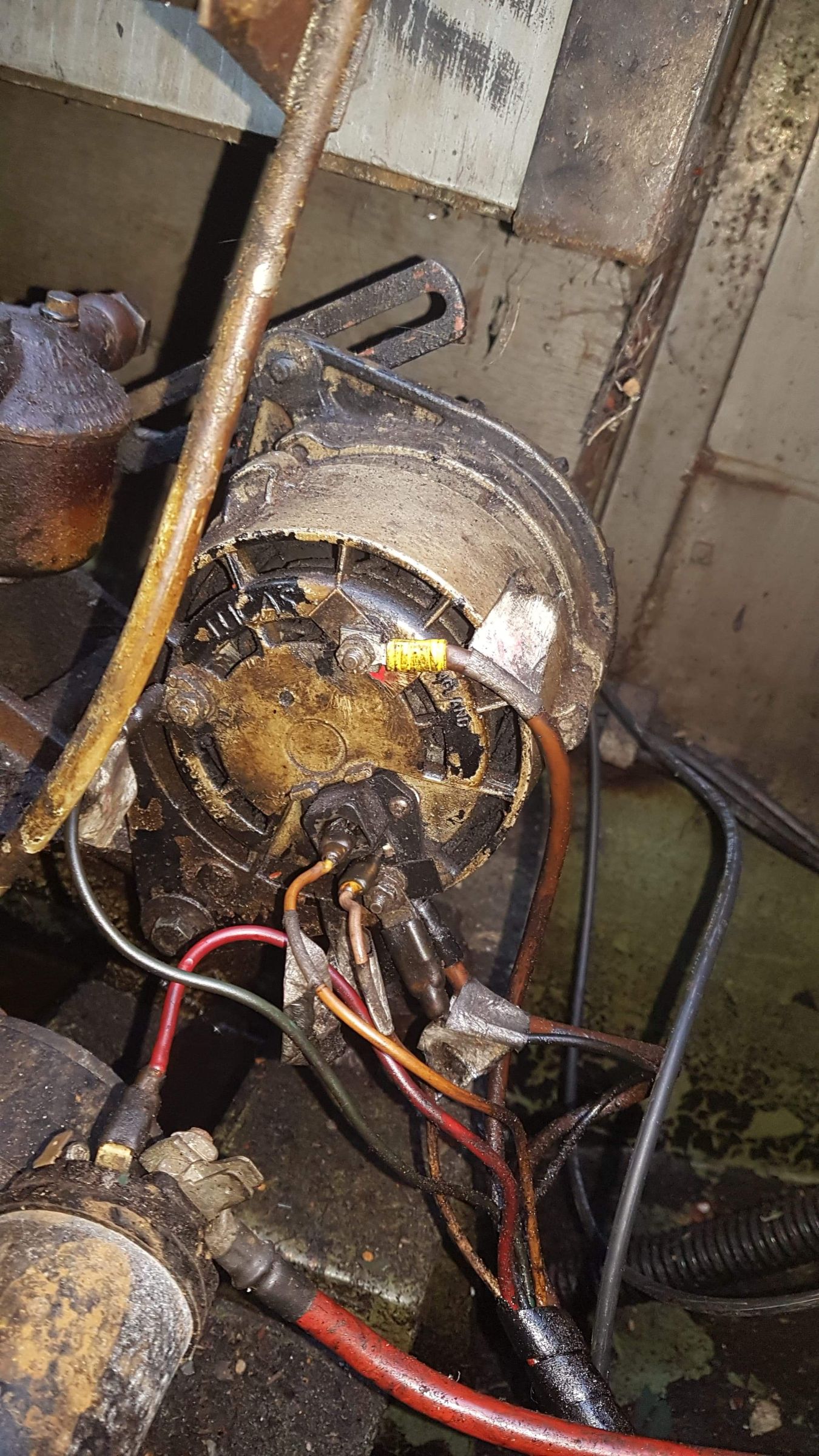
Here is also a picture of current alternator wiring and the wires from the starter solenoid .
-
Ignition system wiring for a127 / Lister sr2
Spoonman replied to Spoonman's topic in Boat Building & Maintenance
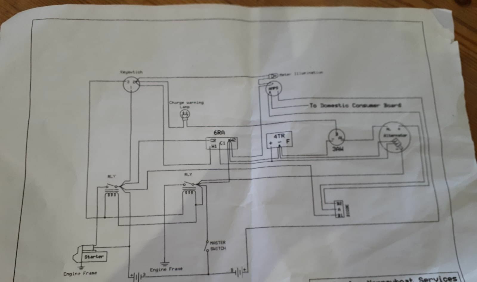
I mean in the starter solenoid there is a Blade terminal with a thinner wire which I'm guessing ultimately leading to the ignition switch , if you have also said that the solenoid can be used as junction box to get an engine battery pos feed. There is also much thicker one which I assume is going to starter battery positive ? (Then one going to the starter motor and and negitive earth one I believe?) Ok so the alternator b+ should be going to the domestic bank first and not the starter. Is there a difference between this and having it go b+ > starter battery > vsr > domestic battery. Hi I will have to check this specifically, but I think it has 3 positions off - on -ignition. I would be looking to install a voltage switch relay after crashing with the ignition system. I will attach diagram of the current electrics system which was apparently done in 2013.I have uploaded this in the past and it has been described as "ancient "😁
-
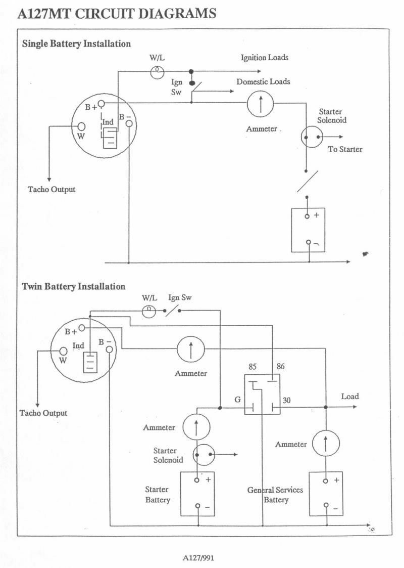
I have posted a few threads in the past about upgrading a broken 11ac Lucas alternator and charging system to a127 type alternator and ultimately putting in vsr charging system in the longrun. In the end our energy needs were met with about 500 watt of solar power to charge the domestic batteries for most of the year so the issue was put to the bottom of the list. Focusing on doing away with the 11ac external regulator , warning lamp relays,alternator relays etc... and installing the most simple igniton system I can, I have found this wiring diagram for the a127 (top one for starter only) and was wondering if it's accurate and if you could suggest any more resources or diagrams . Few questions 1. On this diagram it appears the b+ on the alternator goes via the ammeter and the solenoid + before going to the battery + terminal . However I thought the main charging cable was to go directly to battery + ? 2. I'm a bit confused about which terminals to use on the ignition switch, warning light and starter solenoid and how these all connect together and whether there is negative terminals that need to go to ground? From what I can gather - Alternator d+ > warning light of sufficient wattage > igniton switch "on" terminal Igniton switch "load" terminal > ampmeter> solenoid spade terminal - solenoid + ring terminal>master switch > battery + terminal What confuses me is whether the ignition switch needs to be connected to battery positive directly or does it get power from the spade connector of the solenoid ,as the solenoid is connected to battery positive? 3.I'm also unsure what type or gauge wires I should be using and where any fuses should be placed in the system?For example the b+ charging cable needs to be of suitable thickness got the current and presumably the solenoid large ring terminal to battery + aswell? But for the other connections are the wires thinner and will I be able to reuse most of that from the existing system anyway? 4. Also the current set up has an ammeter, is this optionally?
-
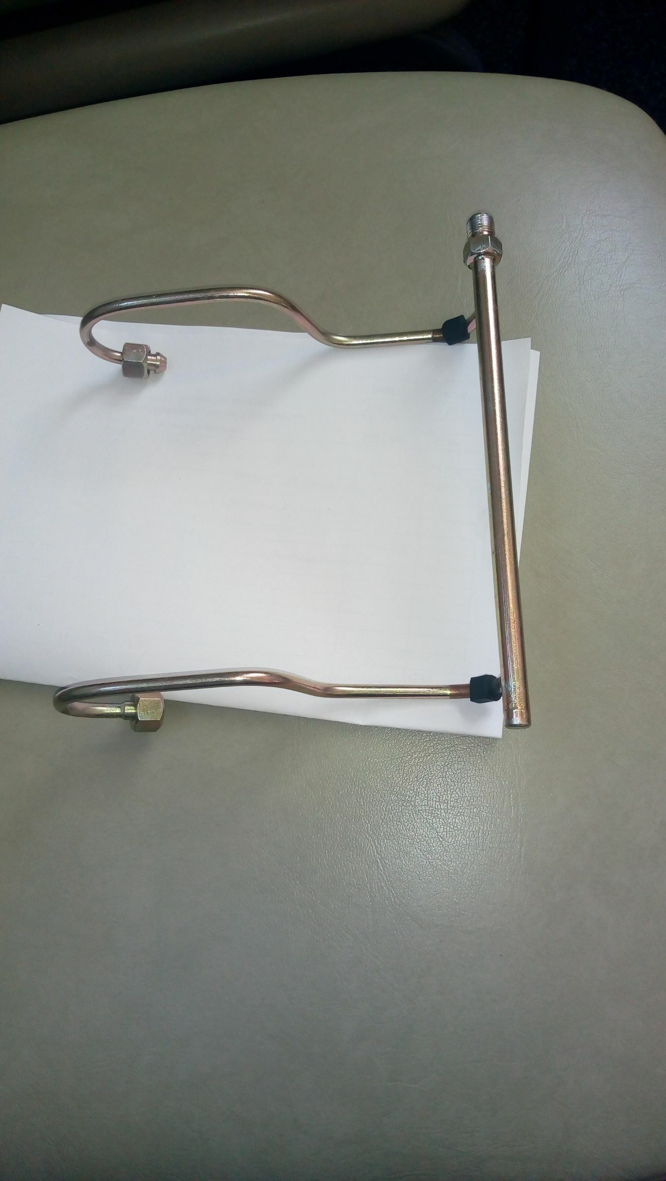
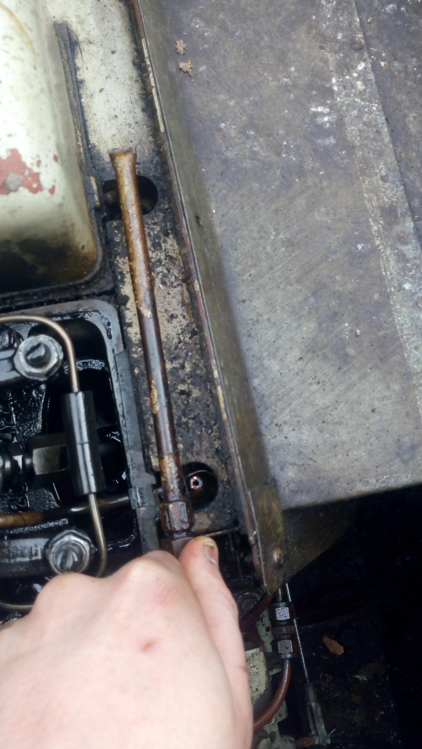
Ok i have my hands on the spill rail but the opening and threads to attach to the fuel lines is on the opposite side - so would be by the second cylinder not the first like it currently is - have i been sent the wrong type of spill rail for the SR2 or am i going to have to modify and extend the fuel lines?
-
I don't think there is any issue with leaking diesel getting in the sump as the engine oil level is normal. Just in to the bilge .
-
The spill rail has cracked at thejoint just outside the 1st cylinder probably due to engine vibrations. Please see the attached pictures Firstly is this something that could be repaired as opposed to replacement and would the both cylinders need to be replaced as they are connected? I contacted listerparts.co.uk (Or any other lister stockists? ) and they said they have spil rails in stock but need to know whether it is a standard or self bleed spil rail? Lastly is this a job a novice could complete my self , or does the whole injector system need to be dismantled first ? any suggestions for a Lister engineer in the northwest?
-
Although i get the process of replacing the fuel filter and the need of bleeding the engine afterwards as far as i can tell there is no fuel lift pump to manually push the fuel through the system when bleeding at the fuel filter. the100 gallon fuel tank is built in to the steel hull at the stern of the boat, going to the engine which is at a lower level so I'm guessing it is gravity fed? how would i go about bleeding the system without a fuel lift pump ? Actually running the engine instead ? Does it require tampering with the fuel injectors ?
-
Bluepoint marine only had 11ft c8 cable in stock so i declined. They didn't seem to think it being c8 would make much difference? I will take the old cable with me to match at the other supplier. As it happens there is a company called cable tec https://www.cable-tec.co.uk/ not far from the litherland services who focus solely on control cables but they don't stock the cables just manufacture to order or repair. So potentially could get the exact one depending on how long that would take.
-
Managed to get the old cable off and its 8ft , stamped on it it says T 8ft A8. At the chandlery in bootle they have a 9ft one on their website as teleflex 33c type c8 control cable Would this be suitable given that one says C8 instead of A8?
-
Thanks for clarifying this ,i was trying to push the throttle lever when in neutral, but when control was at max speed or max reverse it did move and did indeed rev the engine! So disaster averted. I'll have a look about for one of the morse 33c throttle cables at some chandlerys then .i think 5 -6ft would suffice but I'll take the broken one just to be sure. Is it likely i'd be able to find one at a normal garage as they are "universal" not necessarily just marine applications? Thanks again for everyone's help trouble shooting this! Always the same faces that give help when i post on here about the sr2 do really appreciate it. Will give an update if (and probably when😁 )i have trouble fitting the new one
-
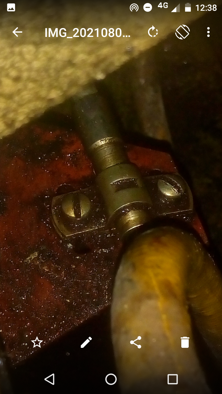
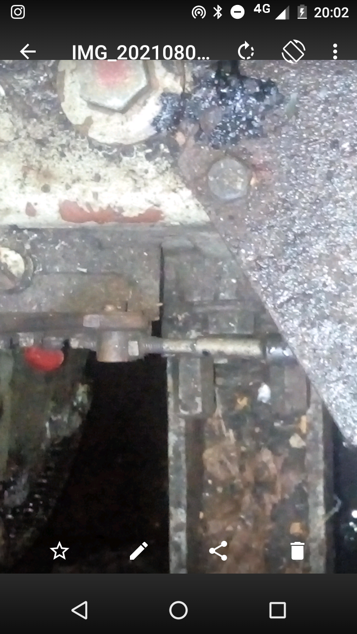
Also see the attached picture of the clamp that the throttle cable goes through. Does this look ok ? This is about 1ft from the throttle lever in the engine Are there any other places that the cable may be clamped and could have come loose?
-
I will test this with fingers crossed. Would i need to remove the throttle cable from the throttle lever pictured first before trying to manually move it by hand because it does not move at all right now
-
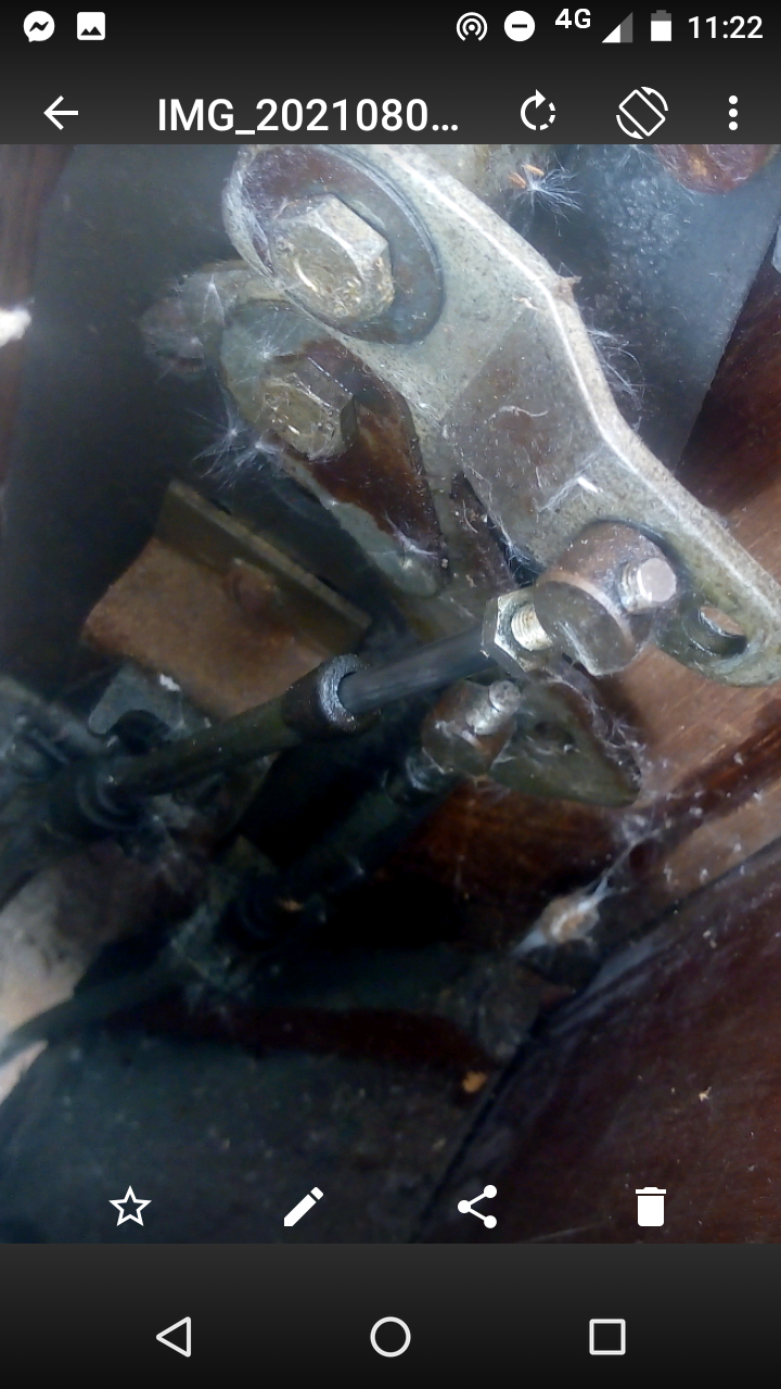
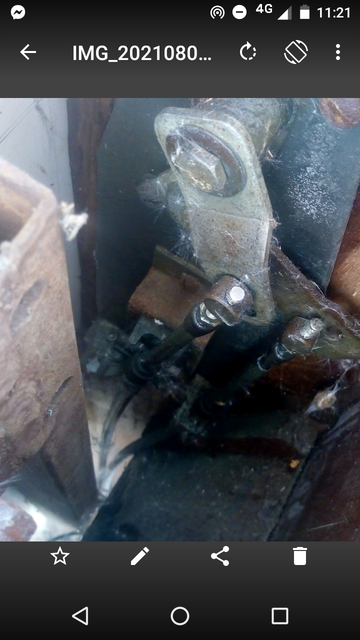
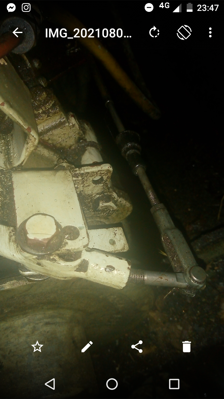
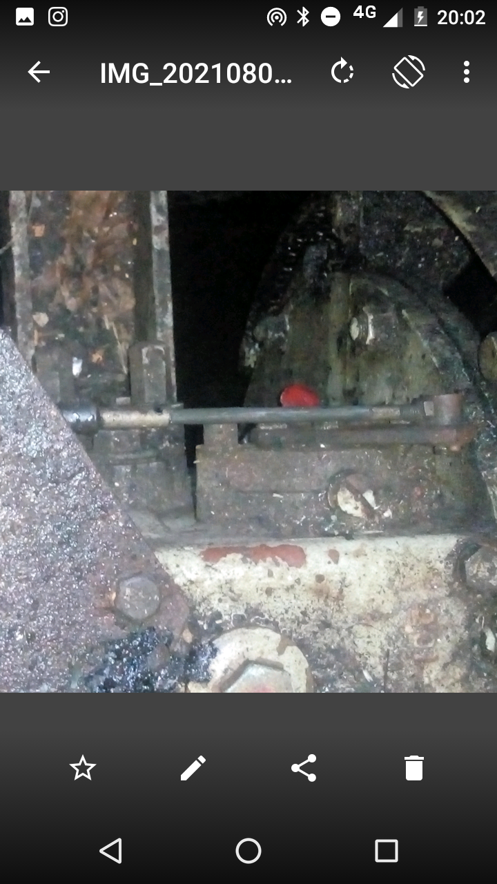
There are two grey cables coming down from the single lever control in to the engine bay - I'm assuming one is for the gear box lever (which is working) the other for the throttle lever. If it was the control lever being broken wouldn't this effect both the gear and throttle lever. Looking inside the control box i believe the throttle cable is still connected to the lever as it will expand and retract when moving from neutral position either up or in to reverse (please see images) so not an issue with the trunnion? At the other end in the engine bay the cable goes through a clamp that is on a small metal plate and two screws either side hold it in place - both of these are tight and the cable doesn't feel lose . Therefore is it looking more likely that the cable is broken inside?
-
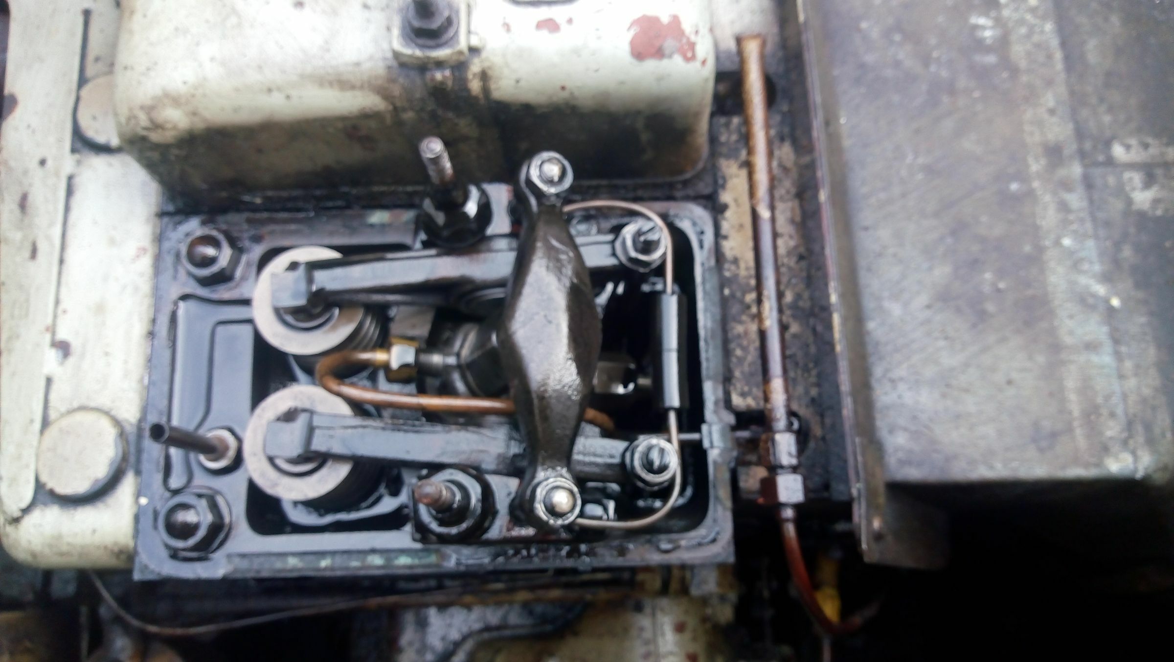
Hi thanks for the reference picture! Please see the attached picture , this is located in a very similar spot to the arrow placed , just to the side of the cam shaft. It seems to be attached to what i would describe as a small metal plate and then that is connected to a flexible cable which I'm assuming is the throttle cable going up to the throttle lever? There is a rubber washer that you can see on the image that is deteriorated and loose on this shaft. If this is the case, this component is definitely not moving when the throttle lever is moved up and down. I do actually have the original Lister maintenance manual and parts manual, what would these parts be listed as specifically? Cheers
-
Yes it is a lh150 gear box. Sorry just to confirm i have the right component please find attached two pictures one with the throttle fully up and one in reverse. So yes i believe the throttle cable is moving back and forth as normal The engine is running fine, sounds as it usually does when running in neutral but the throttle has no effect.