

Cruiser_Boy
-
Posts
39 -
Joined
-
Last visited
Content Type
Profiles
Forums
Events
Gallery
Blogs
Store
Posts posted by Cruiser_Boy
-
-
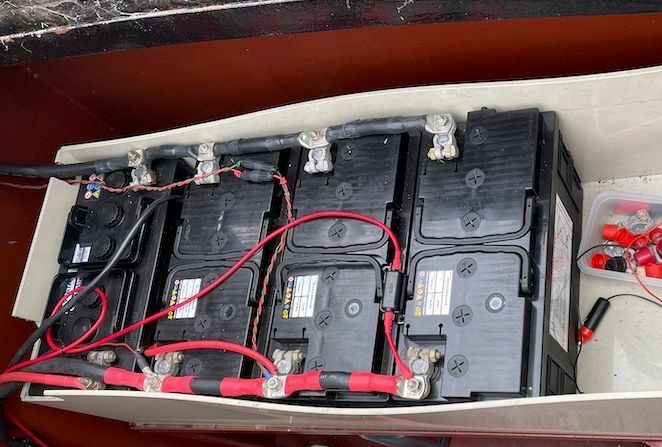
As the title says I have a BSS due in a few months and my main worry based on my reading of the BSS document is my battery container.
It is currently a plastic box large enough to hold 6 batteries that sits on a tray on the swim. Someone replaced the leisure batteries at some time
before I bought the boat and put only 3 in instead of 5. So there is a 2 battery space at the end of the box. There is nothing holding the box in place other
than the weight of the batteries and the massive connector links. The box seems to be a replacement for the original which was just a wooden
board in a recessed rectangular frame, approximately 15mm x 15mm angle iron.
Reading the BSS document the batteries need to be fixed in place and unable to move up to an angle of 45 degrees.
I cannot see any suitable cages or boxes online so will probably have to make my own.
Does anyone have any ideas?
Is wood suitable?
Should I use all metal?
What is a suitable way of holding the batteries down bearing in mind the ends are blocked by the connecting wires. See picture below.
At the same time I am wondering if I need terminal covers. Currently the plastic box has a lid and the decking is just above. I have bought the biggest
terminal covers I can find but they don't even come close to fitting the massive link cables, ~20mm diameter, or the various other 'always on' wires attached
to the terminals.
Is there an alternative method of doing this?
I'm thinking of using some sort of rubber sheet fixed with cable ties.

-
1 hour ago, ditchcrawler said:
On Narrowboats the top of the diesel tank is also the stern deck so they just cut a hole in it and then seal the top ring to the deck with 4 screws drilled and tapped into the deck. The neck just hangs inside the tank.

Yes that sounds like mine. I can see no gap between top of tank and underside of hull. So the pipe can raise up without affecting the seal. I just need to find a way to seal the two part frame. I have to wonder why it isn’t all one part.
42 minutes ago, BEngo said:I think the idea is that the two semi circles butt up against each other to give you a flat surface above and below for the gaskets. I would want a smear of Hylomar or similar between the two halves to make sure that in driving rain or a leaky gate there was no leak path into the tank.
Alternatively get a staple welded either side of the filler and put a bar through with a padlock one end and a bend the other.
N
Yes I was thinking of a welded part when I found this online. I know someone who can weld it but I’m worried about all the hassle of preventing the boat catching fire :-)
-
1 hour ago, Jen-in-Wellies said:
What is the fuel tank on your boat? Is it a separate tank under the rear deck with a pipe, or hose between the filler and tank, or is it built in to the shell, so the rear deck is the top of the tank? This has implications for how the lock is assembled and sealed. Your wording suggests the former.
No I think it is built in I was assuming again which is always dangerous :-)
-
Ahh ok so the Deisel seal is the filler body to the hull surface?
I assumed a separate tube from the tank which the filler body sealed to further down
because filler bodies I have seen for sale have a metal pipe below the cap.
Makes sense if the fuel tank is welded to the hull surface.
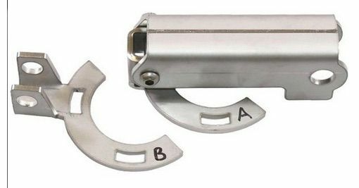
Looking at that photo the lock is in two parts which means it could never be sealed with circular
gaskets.
I may have to shelve this idea.
-
Hi,
I am thinking of fitting a fuel filler lock like the one on Midland Chandlers. See photo.
My filler is a 38mm flush screw cap and the outer containing body sits about 5 to 10mm high above
the hull surface and has 4 screw holes to fix it in place.
Can anyone tell me how this part is removed / replaced please?
Taking the filler cap out it looks like it presses down on a rubber seal although this may be for the cap.
If it does then surely fitting the lock under the cap assembly will hold it higher than before and it may not seal?
The body is 'painted in place' and I am very wary of trying to remove things when I'm not sure what is holding them
in place.
In the engine bay the Deisel tank appears to fit flush with the underside of the hull so there is no internal access to
the filler assembly. In fact I think it is part of the hull as I can see seam welds around it.
-
Hi,
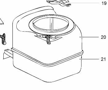
I have had to remove my C200 toilet to work on the flush valve. Unfortunately the screws holding it to the floor were not in the recommended place and had rusted so much as to be impossible to unscrew. I had to cut the heads off to get the toilet out.
Now to get at the valve area and to be able to screw the toilet back to the floor I would like to split the base in two. The Thetford spares list shows the base as an upper and a lower part so it must have at some time in its life been two separate parts - see parts 20 and 21 in attached picture. The lip of the top looks like it clips around the base part but I cannot get it to come off and I don't want to force it too much without knowing how it comes apart.
Does anyone know how to split the two parts please?
-
Ok to finish off this thread I was going to give my experience of the journey. Thanks to the tree blocking bridge 26 on the Ashton canal all my plans have been scuppered.
I checked the alternate going right at Portland basin but that would be an extra 180 locks plus Standedge tunnel. If it had been earlier in the season I might have taken that on but decided not to mid August.
Finally a big shout out to the excellent volunteers who took me down and later up the Marple flight. Also the Bosley crew.
-
Thanks ditchcrawler I did not know I needed to do that. This site keeps putting my answer in the wrong place 🙂
-
8 hours ago, IanD said:
If you can get in, it looks like this...
Looks nice hope I can get in there :-)
21 minutes ago, ditchcrawler said:Don't forget to book the Bridgewater on the CRT web site. I understand Sonny had words with someone not being booked a couple of weeks back
Ooh thanks I did not know I needed to do that.
23 minutes ago, ditchcrawler said:Don't forget to book the Bridgewater on the CRT web site. I understand Sonny had words with someone not being booked a couple of weeks back
Ooh thanks I did not know I needed to do that.
-
13 hours ago, IanD said:
Thomas Telford Basin is locked, access used to be by code which you could usually get from a friendly local, but I believe it's now via keytag so if you moor in there you can't get out on foot or back in again...:-(
Is it for use by general boaters though?
I don’t mind being locked in to moor overnight.
-
8 hours ago, Dartagnan said:
There is a YouTube video by Robbie Cummings showing his ascent of the Rochdale Nine including where he moored the evening before which I believe was just outside the castlefield Marina. Obviously the opposite direction of travel to you but is probably worth a watch as he describes potential issues and solutions.
If I can time it right I will moor up just below the Ashton locks then start on the Rochdale nine early the next morning.
Hopefully then I can choose to stop at Castlefield or carry on onto the Bridgewater and more there.
-
1 hour ago, Stroudwater1 said:
Robbie said he was (&looked) knackered by the end of the day but he was going up them.
Mooring just below the Ashton locks in Manchester seemed fine last month. Thomas Telford basin on the left looked good but it’s in a locked area I believe so not best if you are planning to visit Manchester.
Thomas Telford basin looks fine. I don’t mind it being locked. Nothing against Manchester but I prefer the open country and watching the world go by. My main reason for coming this way is so I don’t backtrack over old ground and and I can go up and down the Anderton lift.
-
Ok thank you everyone.
I interpreted ‘no towpath’ as nowhere to moor. I have been through a lock like that. Can’t remember where it was but it was at a junction. I had to moor on the arm going the wrong way then cross a bridge go up a flight of stairs to the lock, work the lock then come back and turn around to go into the lock.
-
Thanks dmr,
Of course my Nicholson shows towpath everywhere 🙂
Do you remember which bit has no towpath?
Looks like I would be going down so I guess I can just tie the front of the boat to the gate going in but not sure about closing gates coming out.
-
Hi,
I am planning on visiting the peak Forest Canal coming up the Macclesfield from Harecastle. When I return I want to go North from Marple Junction onto the Ashton canal then Rochdale then the Bridgewater Canal to Preston Brook.
This takes me through the Rochdale nine. Is this a problem? I’ve heard a lot of bad stuff about this section. I’m not worried about the work on the locks as long as they function properly I am more worried about where to stay at night. Should I take them on early get through and then cruise well away from the area?
is there anything else I should look out for?
Thanks.
-
When I was looking into buying my Humax Freesat box (HD1100S) I found some information that claimed the disk controller chip was a weak point. Don't know any more than that but if the disk shows as ok on a computer it may be worth getting it checked out. Should be a simple fix for a competent repair person.
-
Thought I would try and add a bit of fun for the season.
If anyone has listened to "I'm sorry I haven't a clue" where they have film titles with a word changed to fit a theme this is my version with a narrowboat theme.
Feel free to join in and add you own titles ?
High Tide
The slow and the ambivalent
Forbidden mooring
Cratch 22 (or anything with catch in the title e.g. catch me if you can)Gone in 60 minutes
Deep Lock 9
Top Gunnel
Blacked Beauty
Navigation impassable -
On 28/09/2020 at 12:27, Loddon said:
Did the new switch cure the problem?
Ooops my apologies I haven't looked at this for months and didn't get an email notification.
Yes fixed now. What I did notice was that when I tested it with plain water I was vastly overestimating when it was 'full' hence emptying it too often. I kept thinking the fix had not worked but it eventually indicated full.
With the light working should be much longer between empties - but much heavier ?
-
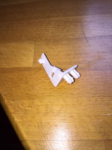
Thanks for all the replies.
For anyone else trying to do this you don't need to undo the screw. The screw holds a clip with some sprung pegs
which fit into the two holes on the Reed switch mount. The third single peg holds the clip in place while putting the
screw in. See attached photo. There looks to be a small gap between the reed and the clip in between the pegs to
put a screwdriver and gently lever the switch off.
Of course I didn't realise this until I had taken the clip off. The screw is Torx by the way.
-
14 hours ago, WotEver said:
Have you shorted out the reed switch to ensure that the light actually works?
No I didn't do that sounds obvious when you say it out loud but the light did work before. I'll try that before I attack the switch :)
-
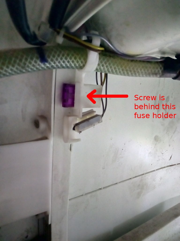
5 hours ago, Jen-in-Wellies said:
The screw is hidden behind the fuse, so no pic. Feels like a cross head. Located here, so you'll gave to go by feel to get a screwdriver to it.
Not sure if there is more than one screw without taking it apart, which I don't want to do. I think it should remove the bracket that holds the fuse and the reed switch, as well as carrying the flush water pipe. From there you should be able to replace the reed switch and crimp on the wires of the new one.
For easier access, the toilet may just lift off a mounting bracket at the rear. Depends how it was installed, but try lifting it upwards. Will be a lot easier to work on. Empty the water tank, or disconnect the flush water too, depending on the exact model you have.
Jen
Hey wonderful thank you!
I tested that fuse as well. Didn't see the screw behind it.
As for fixing I can see 4 rusty screws into the deck so don't want to mess with those unless I have to.
3 hours ago, Loddon said:The usual reason the red light stops working is because the arm in the cassette has become bent due to over vigorous swilling out.
I have had to reset 2 of mine, its a hand in cassette job. Are you sure the arm isn't bent?
Not sure no but I taped a magnet to the reed switch and the light did not come on.
I also used said magnet on the cassette and the arm lifted up and stopped in approximately the right place hence I think it is the switch.
-
I have bought a replacement reed switch for my Thetford C200 toilet.
I have checked the magnets in the cassettes with an external magnet and they appear to be working correctly.
I'd like to replace it without taking the toilet out. The cassette comes out in a cupboard so it is quite a contortion to get at it.
I cannot see or feel the screw that holds it in place. The diagram that came with the new one is useless.
Does anyone have a decent picture of the mounting screw and fitting please?
-
Ok thank you Welsh Cruiser and WotEver.
I am going with fused cable to the batteries and a single isolator switch on the PV side.
-
Hello everyone,
I am close to buying all the parts for my solar system. Due to size constraints it will be a single panel 46V Voc type with MPPT controller.
I will put an isolator switch and fuse in the PV feed to the MPPT and I wanted to route the MPPT to Batteries cable to the existing services isolator switch via
a fused cable. Assuming the services to battery cables are up to it which I think they are.
Now comes my problem. If I have an isolator on both feeds which I think is sensible for safety then it is possible to have both Battery and PV off and then someone could turn the PV on first. The MPPT manual says Battery should be connected first. Its a Victron but I haven't bought it yet.
Is there an isolator switch which could be used that has say 3 positions which allows Battery ON / PV ON, Battery OFF / PV OFF and Battery ON PV OFF but not the 4th option?
Or conversely is it safe to have a switch which allows either both ON or both OFF only? I guess this would allow some minimal time where the PV could be ON and Battery OFF as the switch contacts operate.
Any thoughts ?

Battery box / cage / holder for upcoming BSS
in Boat Building & Maintenance
Posted
I see what you mean but the base of the box is only a few mm into the frame it wouldn’t stop it tipping which is mentioned in the BSS document. So presumably if I had a fixing further up the box that would be sufficient?
Do you mean opposite ends of the bank? In the picture they are on opposite sides.