Craig Shelley
-
Posts
60 -
Joined
-
Last visited
Content Type
Profiles
Forums
Events
Gallery
Blogs
Store
Everything posted by Craig Shelley
-
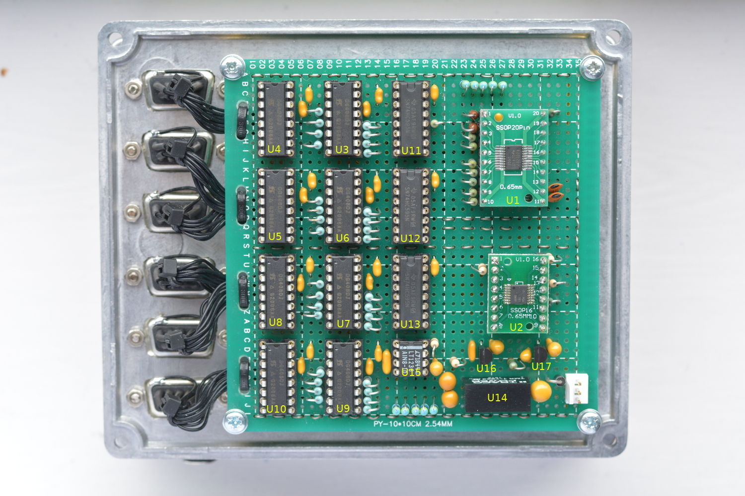
The past couple of months have been fairly heavy going with this project - a final push to get a BMS designed, built and installed. We're beginning to see light at the end of the tunnel. The MK2 prototype is now installed although more work is needed to move the current the measurement functionality across to the new system. Just a quick re-cap on this project so far: 12 CALB 210Ah batteries purchased from EV Support in 2017, and installed with no BMS. The only means of monitoring for the first year was via a 5 digit panel volt meter, and 3 ammeters. A under/over voltage cut off switch was implemented using a BlueSea Systems remote controlled switch wired to two off-the-shelf voltage switch modules. In 2018, a rudimentary means of estimating state of charge was lashed together using a raspbery pi zero and a waveshare ADS1256 module. A few op-amps in a breadboard provide some level shifting and scaling for the ADC. Two years later, this lash-up is still running in on a breadboard on the top shelf of the electrical cupboard. The means of logging data via a google sheet, and plotting using the graphing facility has proved to exceed our expectations regarding reliability and flexibility. It's extremely useful to be able to view the live graphs from anywhere using the google sheets app and it has the ability to share access with family members etc... Time eventually came to build a MK2 unit to overcome some of the limitations, and make a proper installation. Also by this point, I was beginning to get a little nervous about what might be going on with the individual cell voltages. We have only ever carried out spot checks on the cell voltages, but there's never a convenient time to do it. Looking at my spreadsheet, the last measurements were taken nearly a year ago! By this point I have a reasonable idea of what was needed, and what I wanted! I was hoping that an off-the-shelf system would be available by now, as what we're doing isn't exactly novel, and we're not alone in needing a means of precisely measuring multiple voltages. Each time i've looked, the available systems haven't satisfied our specific needs. For instance, many of the multi-cell monitoring solutions are designed for long strings of cells in series, not series-parallel combinations. Also i'm not convinced by the accuracy if the individual per-cell PCB modules as the ones i've seen just rely on the built-in reference within the microcontroller. Having become accustomed to seeing the overall pack voltage displayed with mV resolution and how useful this is whilst observing charge/discharge, I was determined to design something at least as good, but also had an accuracy to complement this resolution. i.e. able to measure the 12V pack voltage within few millivolts. Our setup adds extra complication in that we have 12 cells to monitor. Whilst we could add connecting links between the cells to reduce the number of voltages which need to be monitored, we've chosen not to add the links for the following reasons; Firstly it would be a bit awkward due to the physical layout. Second I believe it might reduce the fault resilience of the pack i.e. 1 faulty cell might then take out 2 more cells. Finally it would not be easy to measure the individual performance of the cells without breaking the links. The system I've ended up designing, for the most part follows a very traditional layout of ADC, instrumentation amplifier and multiplexer. It provides 30 measurement nodes with a somewhat unusual, but flexible multiplexing scheme. It is possible to measure differential voltages between any two nodes; therefore only 5 nodes are needed per battery pack. This scheme enables the polarity of the measurement to be taken in forward and reversed directions. By subtracting the reversed measurements it is possible to eliminate voltage offset of the signal path. A precision voltage reference IC is available via internal nodes 31 and 32 to allow the system to continually self-calibrate. The C code for the raspberry pi is now fully written, I've ended up reusing most of my old python script for uploading the data samples to google sheets. The next phase is to produce some meaningful graphs/dials on the google sheet using the data. I've ended up doing a fair bit of verification work on this prototype unit, even checked it against a reference standard. At 10V the measurement error against the standard was less than 1.5mV. This equates to an error of 0.015%, which is acceptable and well within the spec of the reference IC. It's possible to further reduce this either by using the trim facility available on the reference IC, or by software calibration. I don't think it's necessary to go that far. With the system installed on the boat, a comparison of the sum the individual cell voltages, with the measured overall voltage was found to give a discrepancy of less than 100uV on each of the packs. So after 3 years without balancing, the battery pack isn't looking too bad. We'll need to leave the monitoring system to gather more data across a range of SOC. Initial data with the cells with a light load and at about 75% SOC is showing a maximum cell to cell variation of 2.5mV. There's still a lot of work to do on this project. The next job is to retire the old lash-up system but to do that the battery current measurement signals need to be moved onto this MK2 system. I've drastically underestimated how time consuming this project would be to complete. My biggest oversight so far has been the time taken to build of the prototype unit. I wish i'd gone straight to PCB. After all i'd gone to the effort of properly drawing up the schematic. Due to the way i'd drawn the schematic, I underestimated the sheer number of interconnections needed - well that's 8 days i'm not going to get back! Making the cable assemblies also seemed to take forever. At least the end is now in sight! Photo shows prototype MK2 unit assembled onto lid of diecast enclosure.

-
We ended up using these heated mats. (See photo) They are available on eBay, search for "camper van heating mat" They are rated at 220w/m2. They can be cut down lengthways to fit the size of your enclosure. We have 3 wired in series which, from memory, draws about 1 amp at 12V. In our setup this provides enough heat to maintain the cells above 5 deg C when the ambient temperature is at about -10 deg C. We've fused both the +ve and -ve supply feed to the battery heater circuit so that a single fault e.g short to +ve battery terminal could not cause a meltdown. -- Craig
-
Hello, Apologies in advance if this question has already been discussed in this thread. I've just been trying to determine the "number of cycles" we're putting on our battery pack per year. I have doubts that this data has much meaning because it doesn't factor in depth of discharge, but was trying to get a rough idea of usage/aging. The values i'm getting are in the region of 30 - 40 cycles per year, that's on a ~600Ah pack. Just wondering if these values seem sensible. The method used to estimate this, which is perhaps a little debatable, is to sum the absolute value of the charge for all samples to find the total charge which has passed through the shunts (in+out). Then divide by 2, and divide by the capacity. I also subtracted the measurement drift error which accounts for 3 cycles or so. I imagine there will be other factors which affect cell ageing before the cycles do. -- Craig
-
That's the whole battery, but the measurement point is not right at the battery terminals. It is at the "bus-bars", the junction points of the 3 packs. These are connected with about 1m of 50mm2 wire to each of the 6 terminals. The cells are connected using the proper links, all connections polished before tightening the bolts etc... I would say the majority of that drop will be from the cells rather than the wiring.
-
For comparison, on 12x SE210AHA cells, we drop 0.42V at 130A.
-
Might be worth taking a look at how the heating element is wired. If you're very lucky there might be 2 elements in parallel, which can easily be reconfigured. I'm doubtful though. Other options; to fit a series diode on the heater to half the power, fit a series capacitor in the heater circuit, install a trasformer/autotransformer, lower the voltage at the inverter (some are adjustable e.g. 210-240v), disconnect the heater, fit a lower power heater, mod the hardware to shut off the heater when motor runs, mod the software, choose a different wash cycle, only run the wash when batteries are at a high SOC and warm, adjust the low battery voltage trips to be less sensitive to transients, install more batteries.
-
My guess would be the current surge when the motor starts, combined with the heaters being on is causing the voltage to dip momentarily at the batteries. Does the BMS have any time delay or filtering functionality to prevent a momentary dip in voltage from tripping the battery disconnect?
-
Hi again, I've been keeping an eye on this thread for a while now, and was curious to know how many other people on here are using old cells from Jeremy at EVSupport? On the subject of voltage variation, we've noticed the batteries appear to have a higher "internal resistance" when state of charge is lower. This has caused the low voltage protection to trip out when starting the Dyson. I don't think this is helped by the fact that we often have the inverter in power save mode, so not only is there the surge current from starting the motor, there is also the inrush current of the inverter charging its DC link capacitors. This hasn't been a problem in the past couple of years as we've improved the state of charge monitoring and now maintain a higher SOC during cold weather. I saw, a few weeks back, discussion of cell configuration series-parallel vs parallel-series. All of the points seemed quite valid, but there are a few extras I'd like to throw into the mix. To simplify integration into the existing boat wiring, we went for 3 parallel packs, each consisting of 4 cells in series. The obvious downside is that much more monitoring is required, not that we've installed any yet. But this gives more flexibility for the cells to settle at their own preferred voltages. The danger we envisaged was that one cell becomes out of balance, and suddenly starts to dip in voltage. However, since the cells are all separated between the packs, a single lazy cell causes a reduced contribution to the overall current from its pack. We do notice this as we have independent ammeters for each pack. Sometimes one pack will be providing a lower current than the others. Later on the same day, the same pack might be providing a slightly higher current than the others. It all ends up balancing out, but hints at how imprecise and chaotic the cells really are inside.
-
Trent level to backflow over Derwent Lock?
Craig Shelley replied to Graham Bowers's topic in General Boating
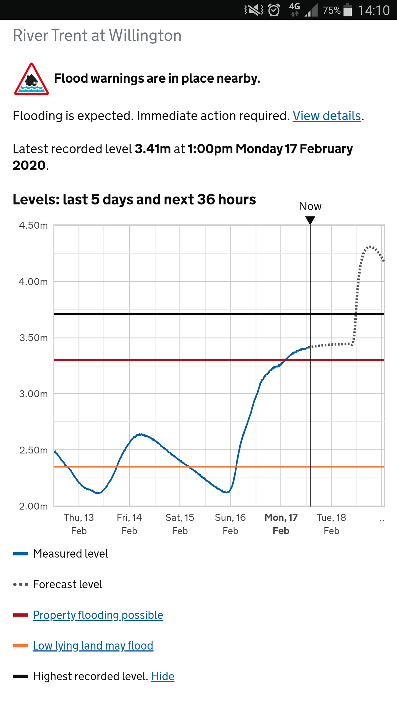
Before it went offline, the Willington gauge prediction was showing a bit of a bump. See attachment We're moored on the pontoon at trent lock, and there are a couple of narrowboats before the floodgates on the cranfleet cut which have started to break free from their moorings. One is currently on the towpath facing the opposite direction - the owner is aware. The other also appears to have broken free at one end, but we haven't seen the owner yet. Access is currently a little awkward due to the water level.
-
On Monday morning (4th Nov), my father was approaching bridge 55 on the Trent and Mersey, and was told by walkers on the tow path to be careful as another narrowboat had come adrift near the bridge. CRT staff boarded the boat as he was passing it, and were securing it to the bank. Unusually, the front doors on the boat were open and there was no front mooring line. Today while we were out walking (different location) my father recognised the same boat and ended up chatting to the owner. It turns out it had been broken into, and ransacked. Among other things, domestic & starter batteries, tiller, windlasses, and mooring lines had been stolen. The owner had left boat quite substantially and visibly secured, and would have required a determined effort to break in.
-
Just catching up on the past few days of messages. I'd advise at least having a panel voltage meter with 3 decimal places of precision. Over time you develop a "feel" for the state of charge based upon the voltage. In our system, we had no bms or cell level monitoring. In the early days, we didn't know what limits to work to, and had very little instrumentation, no ammeters etc... The measured voltage predominantly depends on two things; state of charge and load/charging current. When the batteries are in a rested state I.e. Very little load/charging current for a couple of hours or so, the voltage is a very accurate indicator of state of charge. For us, 13.330V fully charged 13.200V middle ish. 13.100V middle to low, 13.000V we try to avoid going too much lower than this. At either end of the charge curve, you notice the voltage fluctuates much more. For the first few months after installation, we kept the voltage around the 13.2V region. As we later installed the various safety systems, we became a little more adventurous, and carefully explored the upper and lower ends of the characteristic. While charging, the measured voltage will be higher than the resting voltage, and will depend on the charging current and state of charge. Annoyingly, charging current depends to a certain extent on alternator RPM. During the middle three quarters of the capacity curve, the voltage doesn't change a great deal as the batteries are charged. For example if the alternator is kicking out 80A, at about 50% SOC we might see ~13.6xxV for well over an hour. This is where the extra decimal places on the meter really help. The numbers will slowly be counting up as the batteries charge e.g. 13.614 ... 13.615 etc... You get a good feel for the rate of charge. When approaching about 80% (what we call full), the voltage starts to rise quite rapidly. The last decimal place becomes a bit irrelevant at this point because of the speed the voltage is moving. At somewhere between 13.9 and 14.0V, we cut the alternator field and charging stops. The battery voltage rapidly drops to say 13.4xxV. It then takes an hour or so, depending on load current, for the voltage to settle out at the resting voltage value. When choosing a voltage to cut the alternator off at, we were initially very over cautious. The problem with setting it too low e.g.13.7V is that the dependence of charge current on engine RPM means that while traveling, revving the engine might cause the current to ramp up momentarily. This causes the measured voltage to increase, and hence lead to premature tripping. As we got more accustomed, and understood what was happening, the trip threshold was gradually increased. We're now quite happy with a value around 13.95V. Providing the alternator is supplying sufficient current, the voltage does not remain at this high value for any significant length of time. Once the voltage has passed about 13.7V, it really does start to rise quite quickly, accelerating as it goes. The alternator cut off threshold is then tripped cleanly and is far less susceptible to premature triggering. This strategy gives a clean cut off at a consistent state of charge. It would be nice to either control the alternator current to a set value, or compensate for its variation using a software battery model. To summarise; the measured voltage is mainly determined by the battery, which is predominantly dependant on state of charge and load / charging current. With LA batteries, the alternator is required to regulate the voltage while the battery absorbs the energy. In my opinion an alternator voltage regulator is not needed for lithium unless you wish to either fully charge the batteries to 100% using CI/CV mode, or wish to regulate alternator temperature/engine load, or if the alternator current rating is too high for the capacity of the battery pack.
-
The fuse in the +ve is 250A to the motor controller. The fuses in the +ve and -ve charge cables are 50A. The charge cables are 10mm2, and route through the cabin. The negative terminates at the busbar. The +ve goes via a charge relay contact to the starter alternator. If "somehow" the +ve bow thruster battery terminal were to be shorted to the hull, the fault current would circulate via the hull and engine to the negative busbar, then back along the charging cable -ve to the bow thruster battery. Without a fuse in the -ve there is a possibility that the -ve charge cable might burn up. At 10mm2 I'm doubtful it would go that far, but the cable does run through the cabin. There's no harm in fusing it close to the battery.
-
Very good point. Engine to hull would certainly be a much better place for a bonding point. Also often overlooked is fusing the negative charging wire to bow thruster batteries, in case of short from +ve to hull at the battery.
-
Sorry, there's an error in my original post. The prop shaft actually has a flexible coupling, which is electrically isolating it. The prop shaft at the seal is at about +0.5V from the hull. I imagine this is due to the metal the prop is made from. The lost return current can be measured at the engine -ve wire so it must therefore be returning via some other route on the engine e.g. exhaust.
-
Thanks for the quick reply. Would this work for powered DAB aerial? The aerial has two coax cables, and an amplifier power supply wire. The DAB coax is terminated with SMA/SMB connectors.
-
Yesterday, while tidying up some cabling, we discovered the current supply to the radio is higher than its current return. Current supply: ~1A Current return: ~400mA The remainder has been traced to be going down the aerial cable screen to the hull, and then back to battery negative via the engine . This may be unrelated, but when we recently serviced the prop shaft seal and discovered one of the brass components was bright green and pitted, indicating galvanic corrosion. Currently, there is no bonding from battery negative bus bar to the hull. I'm going to install a bond wire with sufficient captivity to handle parasitic and fault currents. It makes a lot of sense to have a bond wire from the negative bus bar to the hull. There is another forum thread which discusses the need for a bond wire in detail. The supply to the radio is shared for TV, and several cigarette lighter sockets. A percentage of the current from these devices is also returning via the radio. Does anyone have any suggestions to prevent current escaping to the hull via the radio aerial?
-
Snap! Same person. He was very helpful, and even made us the cabling and connectors.
-
I guess he got the wrong end of the stick when his doctor prescribed Lithium.
-
Sorry, I was being a little metaphorical. The "pressing of a button" implied taking a manual action such as operating a switch on the dash board. This might be done after engine start, but ultimately, the decision of whether or not to run the alternator is with the helmsman.
-
Agreed 100%. It really isn't too onerous to press a button when you decide to charge up. A simple cut-off when a pre-set voltage is reached is adequate. It's also useful to be able to manually turn off the alternator when for example, you find yourself going against the flow on a river and wish to shed some load from the engine to help keep the temperature down. While travelling, having the domestic loads supplied by the batteries after the alternator has "cut-out" really isn't an issue either, just a different way of thinking compared to LA. The easiest and safest way of shutting down the alternator is to de-energise the field as is a relatively low current and trivial to switch with a standard automotive relay.
-
The instructions for this module are a little lacking, so some time back I wrote these notes: long press set: output logic invert (can only be done if input voltage is not in hysteresis band) enter - toggle between displays: 1 Live Voltage 2 Minutes output has been on for Set key steps through settings: 1 Voltage measuremet 2 Upper voltage, above this relay will turn on 3 Lower voltage, below this relay will turn off (this cannot be higher than Upper voltage) 4 calibration +/- 0.5V 5 dl display shutdown delay in minutes Input pins (top right): When input is active, relay will come on irrespective of invert setting Jumper configures: Short to activate External 5V to activate Notes: At power on, output will always be off. At power on, if voltage is in hysteresis band, it will default to off. Hysteresis band can be configured so that output behaves like a triggered latch by setting one of the thresholds to an unrealistic value Crossing a threshold occurs when voltage has passed through the threshold and next digit is displayed i.e if lower threshold is set to 12.0, then the switch will operate at the boundary between 11.9 and 12.0 if upper thershold is set to 12.0, then the switch will operate at the boundare between 12.0 and 12.1 Power Consumption: 18.67mA relay off 49.5mA relay on 8mA display removed 39.6mA Relay on and display removed 15-20mA from 5V (output of regulator display dependent) 7mA from output of regulator with no display
-
I think it still ought to be doable. MOSFETs are now down to below 500uOhms Rdson. Several in parallel would be needed for 3kw, but still cheaper than a motorised, or latching switch.
-
Are there any solid state solutions to this available yet? Should be a lot cheaper and simpler than latching or motorised switches, in theory. Would still want to have a proper switch for manual isolation though.
-
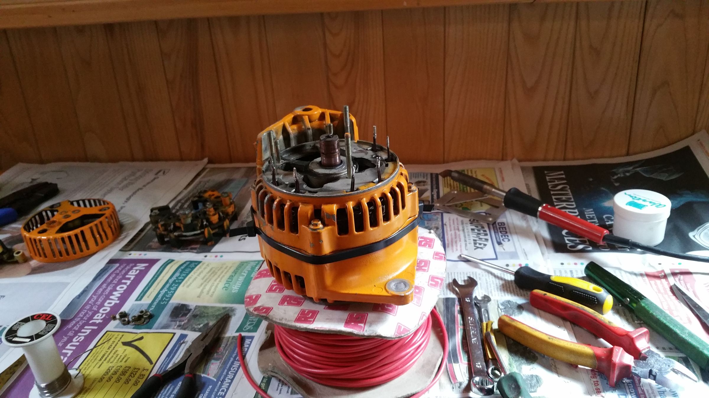
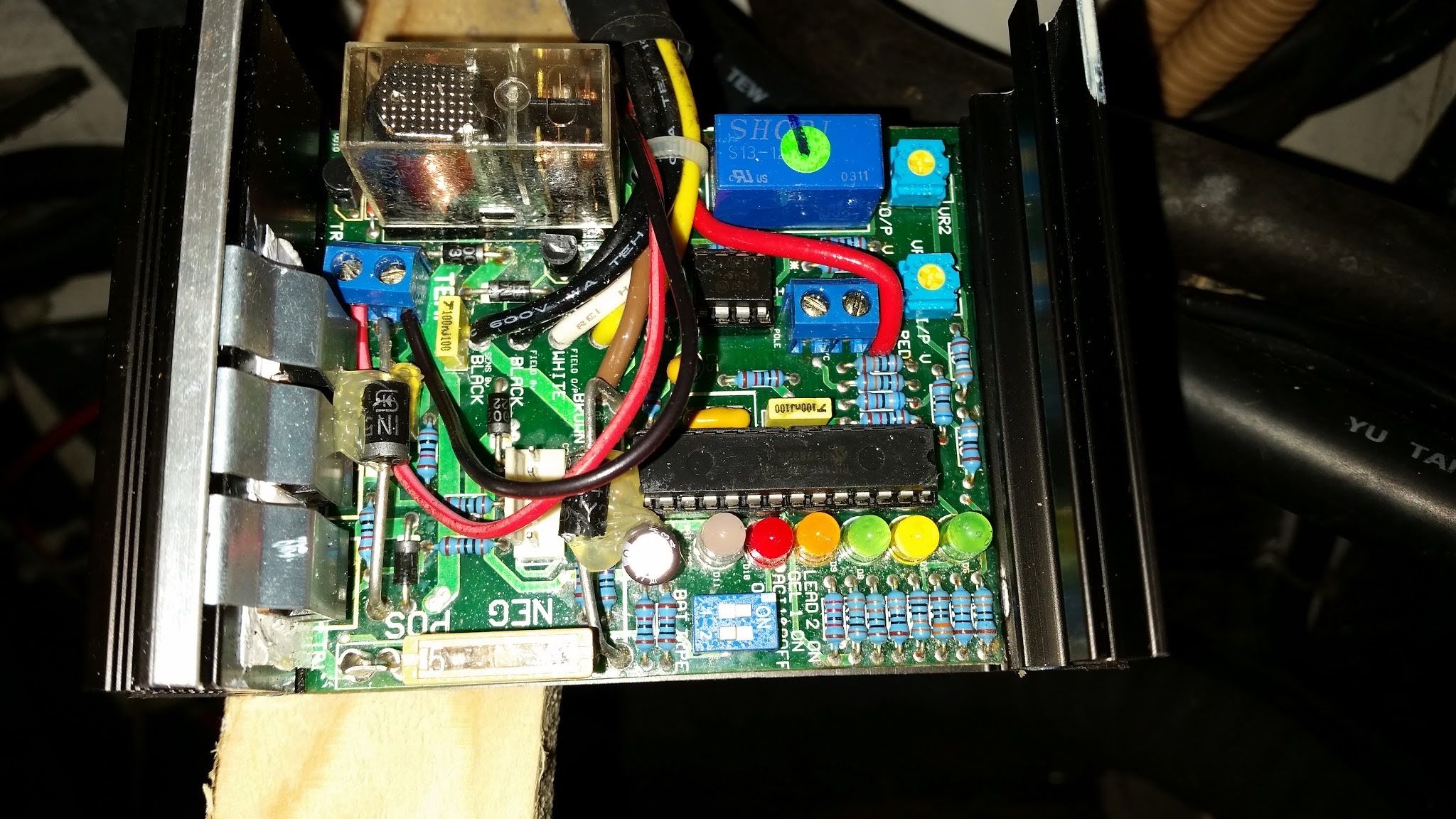
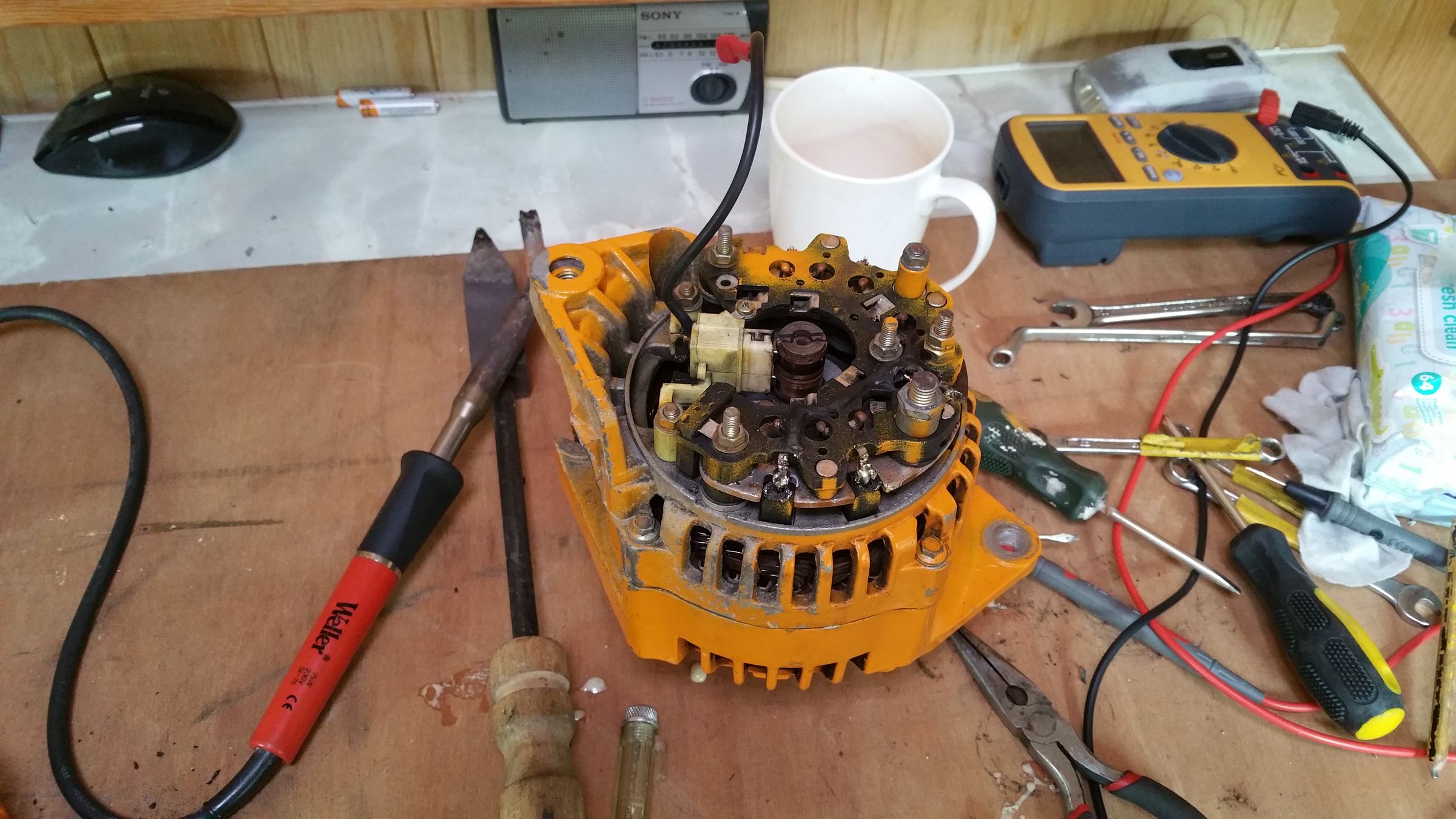
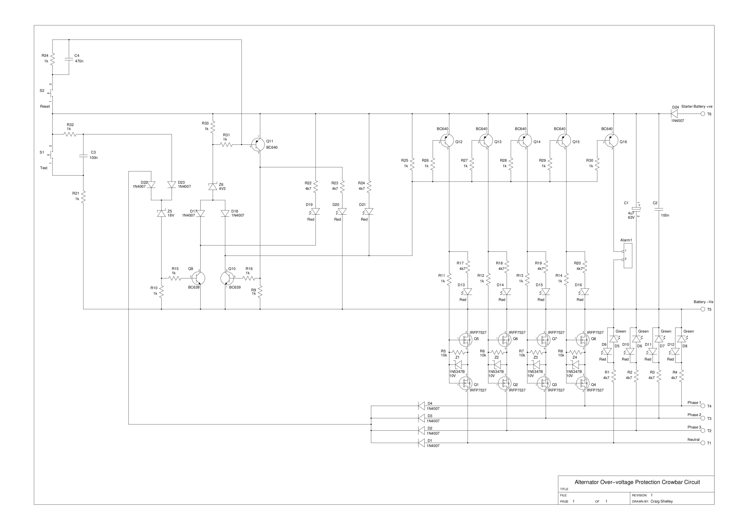
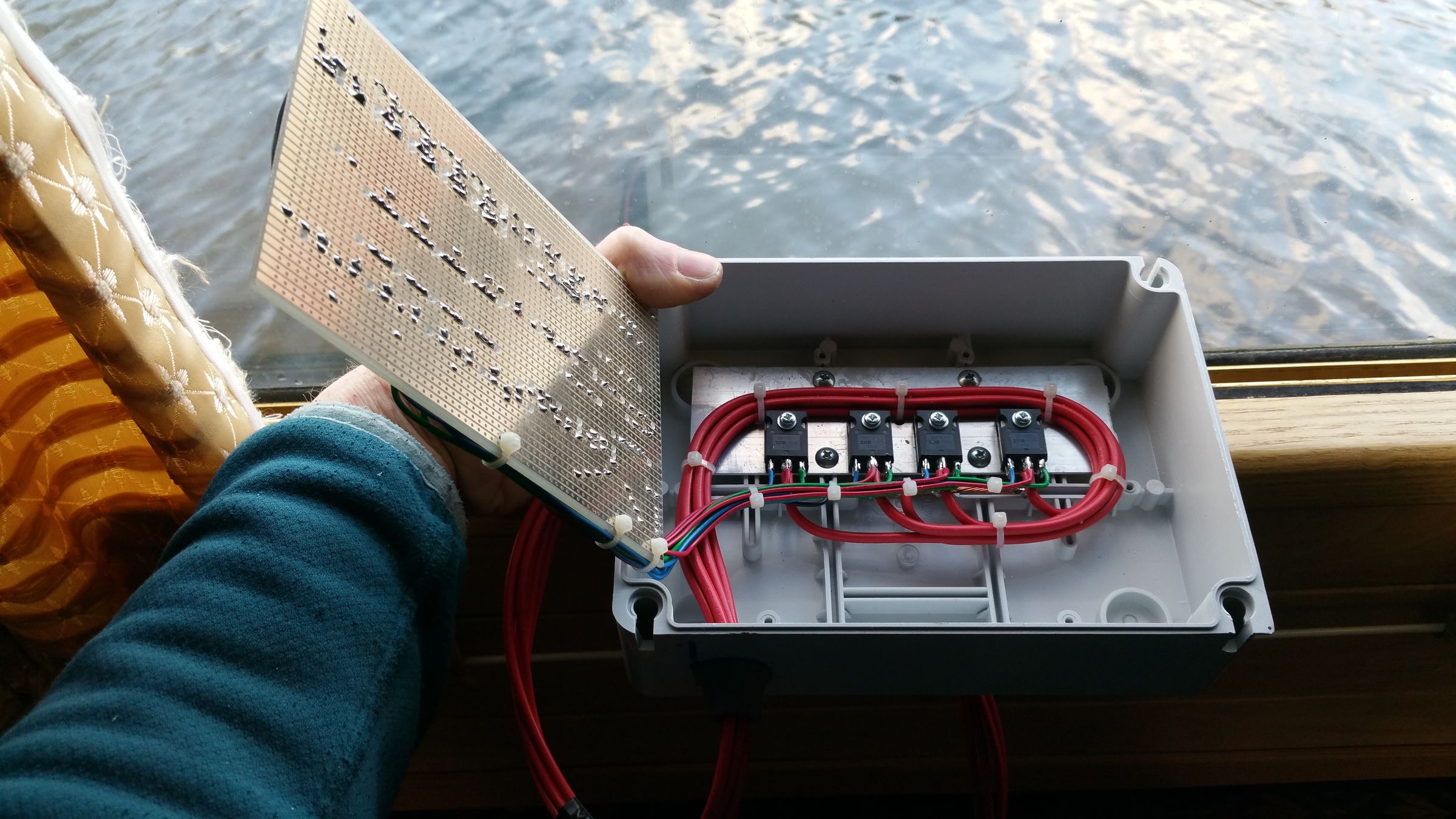
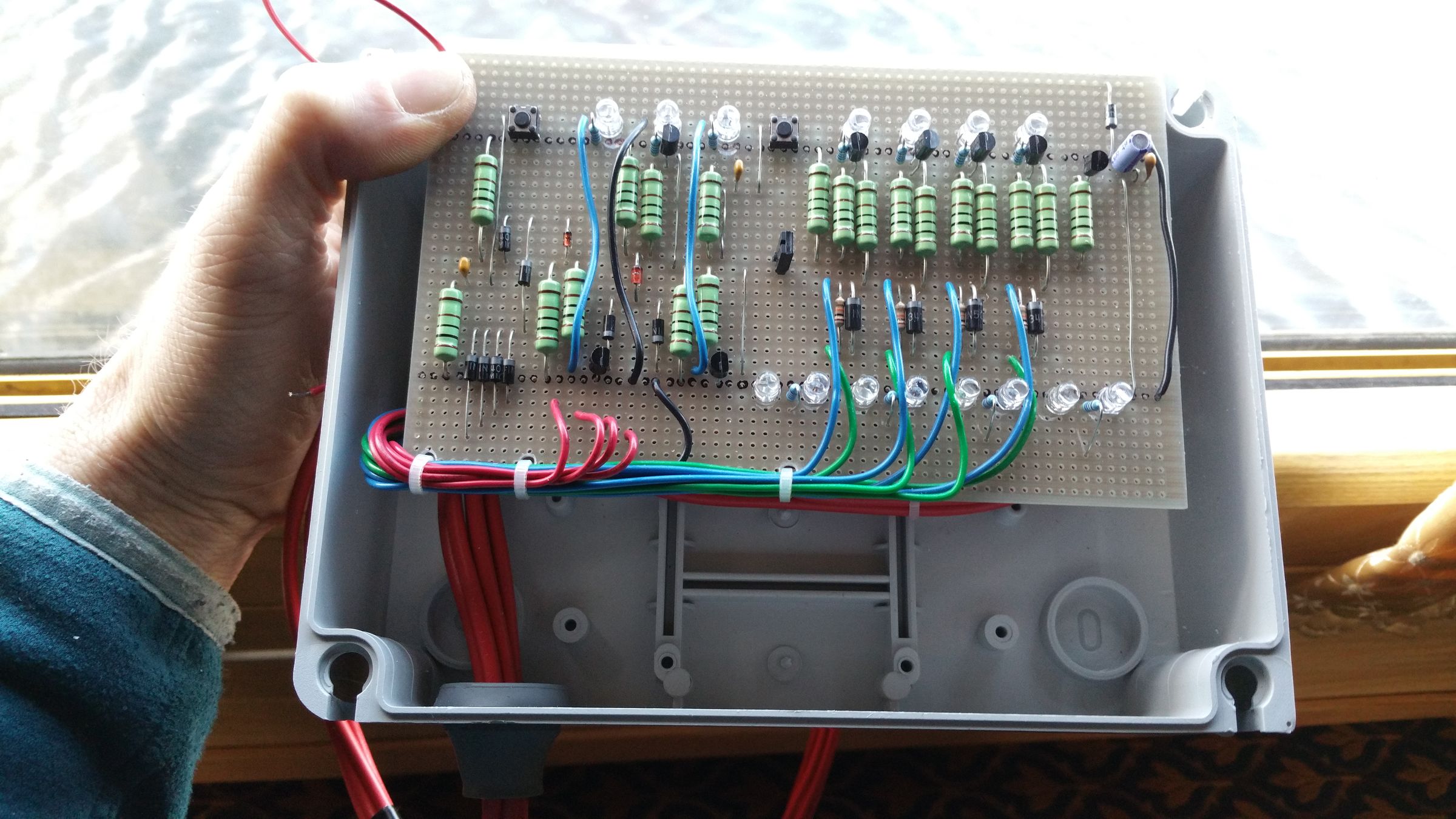
Sorry i've been a bit vague with the explanations. Also apologies for the massive screen-shots, earlier in the thread. I didn't realise they would be scaled up like that. This does get a bit technical, and in some places have still omitted some details to avoid "going down a rabbit hole". Firstly, for battery protection, we have a ML-RBS-7713 remote battery switch from Blue Sea Systems. This was quite a pricey piece of kit, but worth it i think. We had to import it from the US, which was a bit of a rigmarole. It is intended to be used where the batteries are inaccessible, and comes with an illuminated remote switch with sliding guard. On the main unit there is a knob which enables it to be locked off or overridden. The really useful thing about this unit is that the on/off control wire behaves as if the switch is a conventional relay, except that it is internally magnetically latched and draws very little current in either state. Currently we only have protection for the overall battery pack voltage. I hope to improve this soon. We use a couple of cheap modules which can be found on ebay, search "12v voltage control relay". Two of these modules are used, one upper and one for lower trip points. The trip voltage is configured via the buttons and display. Wires are connected via screw terminals. This switching/protection scheme was knocked-up quite quickly using off the shelf parts. I would like to revisit this at some point to make it more fail safe, improve the monitoring etc... If the battery voltage exceeds limits, it disconnects the battery and sounds an alarm buzzer. When my dad bought this boat, the alternator was already fitted with a Sterling AR12VD alternator controller. This system needed modifying in order to behave as we wanted it to. The first trap we encountered was that the alternator's internal regulator was still installed, with the AR12VD overriding it to boost the alternator output. We had to disconnect the alternators internal regulator so that the AR12VD would have full control. As luck would have it, the AR12VD is based on a PIC microcontroller, and the circuit is relatively simple. It was easier just to write fresh firmware to our own requirements, and swap the chip. This firmware has gone through many iterations. We have also made mods to the circuit to install a warning buzzer and an illuminated push-button to enable the charge mode to be selected from the control panel. Additional modifications; The temperature sensor for the AR12VD, which was intended to be installed onto a battery terminal, is now installed on the alternator. The auxiliary relay within the unit, which previously had no use to us, has been re-purposed to control a cooling fan for the alternator. The cooling fan takes cool air from outside of the engine room, and forces it into and around the alternator at the rectifier end. Incidentally, when I first removed this alternator, before any of this upgrade work, I discovered 2 diodes in the rectifier had completely disintegrated. So it probably hadn't been running at full output for some time. I'm a little unsure about posting schematics of this unit due to potentially infringing the design. The circuit is essentially an ordinary alternator regulator circuit but with the reference voltage generated by the PIC. I think the only reason such a high pin-count PIC has been chosen is because it is driving 7 LEDs! As the firmware has evolved, we've ended up just driving the alternator field fully on for charging at full rate, or off for not charging. There is no need to have voltage regulation function. I was half tempted to simplify the whole setup, and just have a relay, providing basic on/off control. Then to use another programmable voltage switch module to cut the field when the batteries are charged. In the end we've kept the AR12VD because it does now monitor the alternator temperature, controls the alternator cooling fan, and performs a few trivial checks on the battery and field voltages. We have kept a kind of "float" mode, which can be selected with a short press of the button, but we don't use it. This alternator is supposed to be 100A rated. Output is engine RPM dependent and I've often thought possibly a bigger crank pulley might be beneficial, but I've not had much luck locating one. The output current is significantly dependent on the the temperature of the alternator. This is mainly to resistive copper losses in the phase windings. Forced air cooling has a significant beneficial effect, and we're able to hold between 80A and 90A at fast idle. From stone cold, it can peak out at about 110A. One thing we soon realised is that alternator output ratings are somewhat optimistic. In an automotive application, the high load current would typically occur after a cold engine start on a cold morning, which would coincide with the alternator's best performance conditions. A 100A rated alternator is therefore not intended to provide 100A continuously. Without the additional forced cooling, I imagine this alternator would have a very short life expectancy as we used to measure temperatures well in excess of 100C. For load-dump protection, initially we did nothing. Except to inform anyone on board not switch off the batteries while the alternator was running. Switching off the batteries is quite easy with the RBS remote switch, so the risk of this occurring is possibly a little higher than average. Also if a fault were to occur which somehow caused the alternator regulator to over-charge the batteries, the battery protection scheme is designed to disconnect them; A good thing for the batteries, but bad for just about everything else. The solution to this is far from trivial. Initially I was considering something functionally equivalent to a Zener, to be connected at the output of the alternator. Something which would prevent the output voltage from rising to a destructive level. The snag with this idea is Power. If, for example, the alternator output were to be clamped to 16V, and if the output were giving a full 100A, there would be 1.6kW of power to be dissipated. There would then need to be another "fail safe" system which could shut down the alternator quickly. Before long, the size and complexity of this approach out-strip any potential usefulness. That's without considering reliability. To add further complications anything installed at the output of the alternator, is also connected directly to the battery most of the time. Leakage currents need to be low. Another thing that was considered was crow-baring the output of the alternator. i.e. applying a dead short if a surge is detected. This sounds initially like a very bad idea however an automotive alternator does not operate in the manner you'd expect. Inside the alternator, there is quite a significant air gap between the rotor and stator, which means the leakage flux in the stator windings is quite substantial. This means that the equivalent circuit for the machine will have a dominant series inductance on each of the winding outputs. i.e. a high-ish source impedance A simplified DC analogy of this would be to imagine the 100A alternator being comprised of a DC source of e.g. 150V, with 1.38 Ohm resistor in series. At 100A, the series resistor would be dropping 138V, leaving 12V for the output. With this analogy we can see that if the output were to become open-circuit, the voltage would jump up to 150V, which matches the real-world behaviour. But we can go further, and answer the question what would happen if the output were shorted out? This can be calculated as 150/1.38 = 109A, so not significantly more than the rated output current. Of course this assumes that the simplified DC analogy is correct. The resistive element in the analogy is in reality inductive, so frequency i.e. RPM plays a part. Also the fixed 150V DC source in the analogy is in reality a variable voltage AC source, with voltage and frequency depending on RPM and field current. But the end result, if the analogy is correct, is that the output can quite safely be shorted out / crow-barred. There is a further benefit to a crow-bar, which might not be immediately obvious. The field winding power is usually derived from the fields via a separate rectifier, usually half-wave. If the alternator is shut down using a crow-bar, the field supply will also be shut down. This will stop all power generation, and will be a safe off state. Further-more, the warning lamp on the console will then illuminate to show the field voltage is low. Ok, there will be a very slight field energisation from the warning lamp, and potentially any remanent flux in the rotor, but i don't believe that to be significant. By comparison to using the Zener approach, where the power would be dissipated directly into the silicon device; crow-baring causes the unwanted power to be dissipated into the copper phase windings which have significantly more "thermal mass", and cooling capacity. The obvious place to install such a crow-bar would be at the output terminal of the alternator, however there's a problem with that. The output terminal is connected to the batteries most of the time (via a fuse) - not good to short out. This could be overcome by installing yet another diode to prevent current back-flowing from the battery to the alternator crow-bar. However, when considering the power dissipation of a typical silicon diode with 0.6V drop, the power at 100A would be 60W! Dealing with that power leads to more complexity. So then I though, how about connecting the crow-bar directly to the phase windings. The downside of this is that 3 crow-bars would be needed instead of 1. The only requirements are that the crow-bar must be fast to switch, it must short all 3 phases simultaneously, and it must have a low electrical resistance. In the crow-bar circuit demonstrated, to achieve the high detection/switching speed, the threshold detection and latch circuits are all implemented with basic transistor logic. (No integrated circuits / micro-controllers). For the low electrical resistance, the phases are shorted using MOSFETs. The circuit monitors the voltage on each phase. Anything above about 19V will cause the circuit to trip and latch. Monitoring all phases within the unit is easier than running an additional monitor wire to the alternator output terminal. LEDs show the presence of voltage and polarity on each of the phases. This gives, at a glance, an indication of the health of the each rectifier diode within the alternator. Green=good, Red=bad/fault. A test button provides a simulated transient, which should trip the crow-bar, and buzzer provides audible indication that it has tripped. There is also a reset button. The only aspect of the design which i've not been able to resolve cleanly is the need of a permanent supply to power the latch circuit. The latch circuit requires practically zero current while in its off state, and only a few mA once tripped, however it is critically important that the supply remain connected permanently in order for the unit to remain correctly in a tripped state in the event of a surge. We have this connection made to the starter battery (un-switched) via a 1A fuse. Attached files 2x photographs of Alternator being re-built, 1x Photograph of Sterling AR12VD with cover removed, 1x Schematic of Crow-bar circuit, 2x Photos of crow-bar unit partially built. The links to the youtube videos posted earlier in this thread demonstrate the trip threshold, the test and reset function, and a demo running on an engine with batteries being remotely disconnected while being charged at 100A. I'm willing to share the source code for the alternator controller, however I don't know how much use this will be, given that we have modified our unit quite substantially. Best Regards, Craig
-
That's pretty much what we've done. They are used traction cells from Allied Boxer vans. 12 x 210Ah cells with were selected from a set of approx 30 to have similar capacities. As expected, their capacity is reduced somewhat from the rated value, but still more than adequate for a domestic supply. We never fully charge or fully discharge them, so balancing hasn't been an issue so far. The weight difference caught us off-guard. Ended up getting some storage heater blocks for ballast, and moved the beer to a different cupboard.