Col_T
-
Posts
509 -
Joined
-
Last visited
Content Type
Profiles
Forums
Events
Gallery
Blogs
Store
Everything posted by Col_T
-
Chaps, Given the second diagram as a starting point, I'm trying to come up with options that will allow the inverter / charger to charge both the domestics and the engine battery. The only thing that I can come up with is a new +ve connection from Dom 5 to the Motor Battery, but this would result in a single battery bank which isn't what I want. So, I could put an isolator switch into the new connection between the domestics and the motor - 'on' allowing current to flow between domestics and motor, for when the boat is on shore-line, 'off' separating them, for when we're not. I'm not terribly keen on that idea as it just complicates things, and I can practically guarantee it'll get left in the wrong position at some point. Other options, of course, include adding a new charger specifically for motor battery, and fitting solar to the boat. Given that the boat spends most of it's life in a marina connected to a shore-line this doesn't seem wholly appropriate. Any suggestions?
-
We have the 1500w version on our boat, and have had no problems with it at all. That said, we only use the boat some weekends and two or three times a year for a week at a time. Ours does hum, regardless of whether it's running in inverter or charger mode, but then the 12v fridge hums and creaks a little too - sometimes in a pleasant harmony, with the fridge doing the descant, sometimes in a discordant, modern jazz stylee when the fridge goes all creak, rattle and groan. Interesting place, our boat!
-
Thanks for that, Alan, which confirms that I, almost, understood it correctly. I used it in the sense "I don't have anything further to add, but may still pop-in to see if anyone has made a comment that improves my understanding a tad". On that basis, I'll say ta-ra for now, and y'all have a good day, now!
-
Thanks for that, Tony, and for all the other help you've given me both directly (answering my questions) and indirectly (answering other people's questions). Much appreciated. Over and out.
-
Many thanks for the replies, chaps. Thanks for confirming this, Tony. I've checked the original scraps of paper which I used when drawing this out on the boat, and I can see no obvious mistakes, but I'll check again next time I'm on board. In a perverse kind of way, this is good news as it suggests that I am starting to get some kind of idea about this electrickery stuff! Who said the age of miracles had passed?! A sound comment, Alan, though I fear my drawing has led you astray somewhat. The 'red' cables you refer to are shown, in the photo, at the point MEB 2 on the diagram (top left corner). From there the circuit goes via Isolator Switch (R) => 12v Distribution Panel => the -ve side of Dom 1. Typing this on a laptop, it's easy to see where the circuit goes though, having previewed it in tablet and phone mode, I can see that it is far from clear. Another question - I've read in a number of threads that the AC and DC hull bonding points should be in close proximity to each, though not use the same physical point - what is the reasoning this, please? I ask as the AC hull bonding is a good couple of feet away from the DC bonding point on the engine bearer and I wonder whether there is any advantage to moving it closer.
-
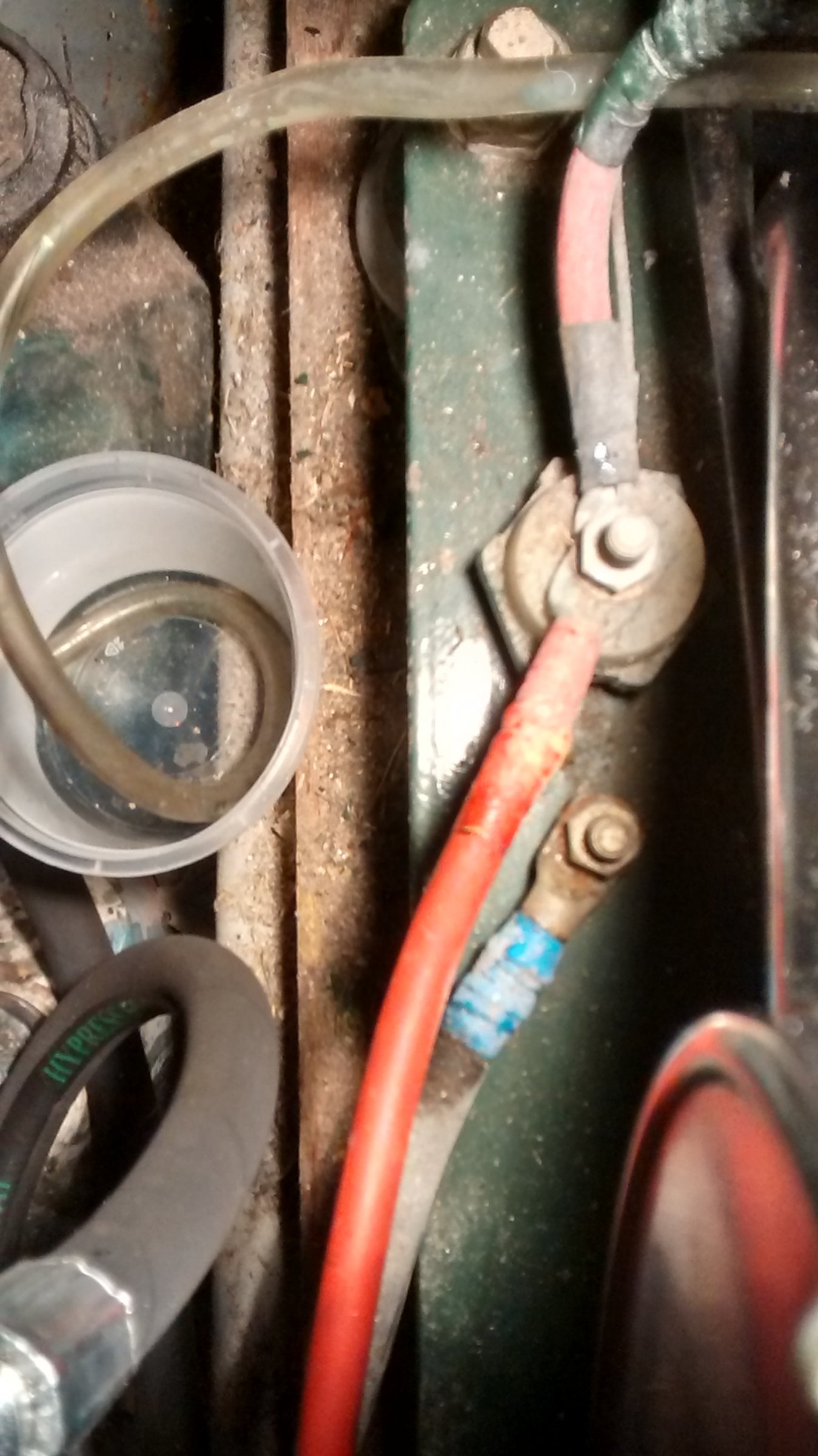
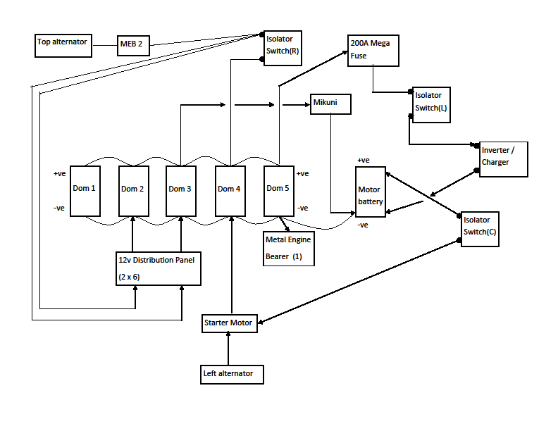
Thanks for this, Tony. I've redrawn the diagram as you suggested, which comes out as below: In all honesty, this just makes me realise that I'm not entirely sure how the battery charging circuit, from the Inverter / Charger, works as originally drawn or, indeed, as drawn in this revised version! Any comments would be much appreciated. I've attached a photo showing the two -ve connections to the metal engine bearer which will, hopefully, make things a little more clear. I'm also hoping this will confirm that MEB 2 is not a dead short though, again, comments would appreciated. Oh, the separated by about 6 inches, in the OP, is well wrong; probably not even 6cm!! Thanks for your help.

-
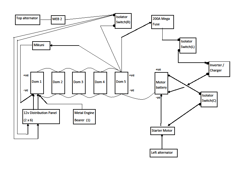
I've spent a bit of time trying to trace the 12v electrics on the boat, which has resulted in the diagram below . . . . . and a number of questions! The domestic batteries are low maintenance, sealed lead acids and the motor battery is an open cell lead acid battery e.g. gets topped-up as and when required. The motor is a twin alternator Beta BV 1505. There are two connections onto a metal engine bearer [Metal Engine Bearer (1) and MEB2 in the diagram above]. These connections are onto the same physical engine bearer, though not the same physical connection point being separated by about 6 inches. Questions:- This relates to the left alternator / starter motor circuit. My interpretation is that the circuit goes from the starter motor to the -ves of the battery marked as 'Dom 4' => 'Dom 5' => Motor Battery and then continues from the +ve of the Motor Battery through the Isolator Switch and thence back to the starter motor. This seems a little odd, as I would expect the -ve from the starter motor to go straight to the Motor Battery, so I plan to alter this part of the wiring but is there any reason why I shouldn't? This relates to the Mikuni water heater circuit. My interpretation is that the circuit goes from the +ve of the battery marked as 'Dom 3' => the Mikuni to the -ve of the Motor Battery and then back along the -ves of 'Dom 5' => 'Dom 4' => 'Dom 3'. I'm not convinced this is best practice, so I plan to alter the wiring so that the -ve goes direct from the Mikuni to 'Dom 3', so that both connections for the Mikuni are to the same battery. I also plan to move the existing connection, to the 12v distribution panel, from 'Dom 3' to 'Dom 4' to reduce the number of connections on the 'Dom 3' -ve, just so that there are not too many connections on any single terminal. Does all of this sound sensible? Not shown on the diagram is a connection that goes from a hull earth bonding point to the Inverter / Charger (a Sterling Pro-Combi 1500w modified sine-wave affair), and another connection that goes from the hull earth bonding point to the boat side of a Galvanic Isolator . I have yet to find any DC connection to a hull earth bonding point, or is this adequately dealt by the connections from the battery DC to the metal engine bearer? All / any comments welcomed, and apologies for the basic nature of some of this but I'm trying to understand this electrickery stuff, and, with the first two questions at least, and trying to check my understanding. Thanks in advance.
-
Just out of curiosity, LadyG, could you post a link to the lithium battery bank that you have, please? I could find a use for something like that!
-
Thanks for this, Robbo. Is there any logic behind the 70mm2 recommendation or is it a case of experience saying that seems right? Also, I guess that re-wiring the inter-connects, right up to the charger / inverter, removes any advantage offered by the other inter-connect options detailed on the SmartGauge site??
-
Thanks for all the replies, chaps, very much appreciated. To answer a couple of questions:- the battery bank comprises 5 off 110 Ah sealed lead acids connected to a 1500w Sterling Pro-Combi charger / inverter, the boat is 12 / 240v. I don't have the manual to hand, but I think that the Pro-Combi manual specifies 35mm^2 cable to connect that unit to the batteries so I'm rather hoping that is what has been fitted, as any new cabling would be in that size. As an aside, would quality cable have specs marked in the covering?? As far as other inter-connect options are concerned, I know that the SmartGauge site details some but those are all for even numbers of batteries, which ain't what I've got. The possible requirement for bus-bars came from me trying to diagram the electric circuits and deciding that it didn't really make sense, but then that might be because my understanding of electrics is still very, very basic! To keep things clear, I'll start a new thread for that. Once again, thanks for the help.
-
Reading various threads, and other websites, has given me the idea that all battery interconnect cables should be the same length. Is it okay to have the length of positive interconnect cables different to the length of negative interconnects?? The reason for asking is that I am considering connecting the batteries to bus-bars (one for positive, one for negative) but, because of limited space, both bus-bars would need to be on the same side of the batteries. This results in the interconnect cable from each positive terminal being longer than the interconnect from the corresponding negative terminal as the positive cable would have to go over the battery.
-
Okay - thanks for that.
-
I thought one of the advantages of a PRM 150 is that, being a hydraulic box, you could go direct from forward to reverse, or vide-versa - am I wrong??
-
Is there a problem with starting to recharge as soon as you can? I thought the collective wisdom had decided that charging as soon as poss. removed the likelihood of irrecoverable sulphation.
-
Ordered it on Saturday, from Amazon, standard delivery and it arrived yesterday. Plugged it in to-day and it found the home wifi network no problem, so now I have to try and be patient until I can get to the boat to try it there. It is tiny, so sticking it in a window should be no problem at all.
-
As you've said in Wotever's thread, cheap enough to get one on spec, as it where, so that is what I shall do! Thanks for the help.
-
Thanks, Robbo.
-
The marina where our boat has moored has a wifi network that is free to moorers, which is good. Unfortunately, neither my wife's smartphone nor IPad can connect to the wifi network from inside the boat, not so good. We have used the phone as a hot-spot to connect the iPad to the Internet but would prefer to use the marinas wifi instead of my wife's data allowance. Does anyone know if there is some kind of device, preferably with an external antenna, that will allow the phone and / or the iPad to connect to the marina's wifi??
-
The blurb says not to "use trickle charge with these batteries". Anyone got any ideas why trickle charging is a no-no??
-
Thanks for all the replies, and apologies for not responding sooner. I know from other threads that battery capacity falls as it sulphated and, because I hadn't understood things properly, I guessed that 'fully charged' tail current would fall as the actual capacity of a battery falls. As I've learned from this thread, the 'fully charged' tail current will actually increase, and should be measured when the battery charger is in absorption mode rather than trickle charge, which is something else I didn't know. Many thanks to all for the contributions.
-
Thanks for this, Tony, especially as your "failure to fall" comment is what I kind of expected. In all honesty, "trying to be over exact" seems to be one of my dominant traits, or so my wife tells me!!
-
Many threads talk about tail current being the most accurate way of determining when a battery is fully charged e.g. charge until tail current falls to a specified percentage of the original battery capacity and doesn't fall for a further time period. 2% and three-quarters of an hour seem to be favourites. We know that battery capacity falls as said battery becomes more sulphated, so it would reasonable that the tail current value also falls. Example, using the above, I would expect to charge a new 110 ah battery until tail current didn't fall below 2 amps (2%) for 45 minutes, and charge a 110 ah battery that now had 82 ah capacity (75% of original) to 1.5 amps for 45 minutes. Is this correct, or have I misunderstood something??
-
There have been a number of threads recently about charging batteries and sulphation. I have got the impression that, to minimise sulphation, best practise is to charge every day or failing that, as often as you possibly can. The Smartgauge then reverts to being an indication of how charged your batteries are, expressed as a percentage, in which case the unit that displays a lower than actual state is the one to retain.
-
Did you ever find the access point to the cabin bilge, the 'secret door'? Only asking as the bedroom is at the stern on our boat, and the secret door is hidden under a board in the bottom of the wardrobe. hope this helps.
-
Thanks chaps, that's cleared that up for me.