jonesthenuke
-
Posts
922 -
Joined
-
Last visited
Content Type
Profiles
Forums
Events
Gallery
Blogs
Store
Everything posted by jonesthenuke
-

Plate heat exchanger to heat radiators from engine.
jonesthenuke replied to JoshS's topic in Boat Building & Maintenance
I am sceptical about this. As well as the solar heating systems that I mentioned in my earlier post I have a similar heat exchanger which interfaces a wood fired range cooker to the central heating system in our house (this avoids interactions between the two systems). I have used this for over ten years. The cooker can provide about 12 kW of water heating. The temperature difference between the two water systems is very small, typically less than 5C (measured with an IR gun). I suggest the OP looks for the design information for the proposed heat exchanger, or a similarly rated one. Note they should be arranged in contra-flow to get the lowest temperature difference. -
Plate heat exchanger to heat radiators from engine.
jonesthenuke replied to JoshS's topic in Boat Building & Maintenance
I suggest you need to place the HE in parallel with the skin tank rather in series with it as the small ports out otherwise restrict the flow to the skin tank. Probably not a good thing to find out next time you are cruising a river against the flow. I have used these for domestic solar water heating projects and they are very good. Add valves to make it easy to isolate and drain etc. Filters (strainers) are a good idea. The comparatively high rating in relation to the radiator load means that some fouling will have limited effect on overall performance. Take care for find pipe fittings where you can have rubber seals acting on the flat ends of the pipe connections as its harder to get a good seal on the threads as they are parallel. -
This post cannot be displayed because it is in a forum which requires at least 10 posts to view.
-
I would certainly not use spray foam, fire rated or not. At a high enough temperature the foam will either melt or in the worst case ignite. It would be much better to use glass or ceramic fibre insulation as it is fire proof rather than fire retardant. Our chimney interspace is insulated with rockwool style insulation. Another option is the woven glass fibre tape used to wrap exhaust pipework, but it would be fiddly to fit it.
-
Do you mean the valve was fully opened and you have moved it from that position? If so you have have the pump sucking air in through the gland on the valve. If you shut the pump down does the leak from the valve look worse? If so, try fully opting the valve and see if the leak reduces. If its taking baldly, shut off the pump and fully close the valve and just open it when you want to use water (a nuisance but it limits water damage until you can get the valve repaired/replaced). In any case I would get a spanner and tighten the gland nut (shown circled in your original post).
-
Taking your comment "there is not a clear opinion whether the gauge measures at level A or B". Level A is irrelevant in terms of measuring the tank level in the way proposed, the siphon section has no impact on the pressure as the two sides cancel each other out. This assumes the upstaged section is full of fuel with no air/vapour spaces (which should be the case as the engine would be pulling fuel through when running). The pressure at B under static conditions will be proportional to the difference in level between the top surface of the liquid in the tank and level of the sensor and the density of the liquid. As it's easier to measure positive pressures, the general approach is to place the sensor below the bottom of the tank so that the pressure is always positive. Where this is not possible then the measurement is limited to tank levels above the height of the sensor and this would need to be taken into account when calibrating the system (noting it would match the usable tank contents in the diagrams shown. If the sensor can work with both positive and negative pressures then this restriction is overcome but the sensor will be more complex/expensive. The significant problem with etc design in the sketch is the location of the sensor on the fuel suction line. When the engine is running The pressure at the sensor will be reduced due to the pressure drop along the pipework and the additional pressure drop across the filter. This may be significant, depending on flow rate and the degree to which the filter is fouled. Consequently the measurement will be of little use when the engine is running, however, the reading would be correct when the engine is shutdown, thus its not all bad. I would note that the fuel flow rate for a narrowboat will be low (say 1 litre per hour) and the filter capable of much higher flows the error due to engine running may be limited. If you want to proceed with this system, install the sensor low down and below the bottom of the suction line in the tank if this is practicable. Also install it between the tank and filter if this is possible. This will reduce the problems noted above The best solution would be to connect to the tank directly. Do you have a drain line or fitting that would allow this to be done?
-
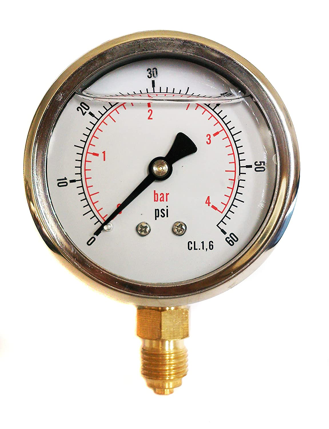
The gauges are not filled completely as they would then be subject to internal pressure changes caused by the fluid changing volume when the ambient temperature changes. This would them change the reading of the gauge. In the extreme this fluid expansion could cause the case to fail.
-
Glycerine filled gauges are common. the liquid damps the mechanism, reducing wear and providing a stable riding if the pressure is fluctuating. Regarding the size, it depends on what the OP wants to do (I am not a mind reader). A very small gauge (say 40mm) fitted to the top of the pigeon box is ok but hard to read due to size at the expected distance form the steering position. If a gauge is fitted to the roof adjacent to the end of the pigeon box rather than on top of the box then it can be bigger (and easier to read). The gauge is showed was an example for he OP to consider, that's all.
-
What size gauge do you want and what range, 120 psi may be too high? Tere are some on Amazon, 100mm dial, stainless case 0/60 psi?

-
OK but please note I am not saying run at max revs, just rather more than tickover and soon after starting the engine. It is the only easy way that you can check if the alternator is capable of delivering its rated output (or near to it). I suggest you start the engine and then increase the revs bit by bit until you see no further increase in current and note the peak current value. You do not need to be in gear for this, and shouldn't if moored in any case. Without doing a check like this it is hard to tell if your alternator is underperforming or if its all down to the charging regime you have described, which does appear to be inadequate based on what you have posted so far.
-
OK so what happens if you start the engine first thing n the morning (so batteries part discharged) and you promptly increase the revs to say 2500?
-
You say you see 30-40 amps when initially running the engine? Are you running the engine fast enough? Tickover will not give probably not give full charging current. Try increasing the revs immediately after starting and check if the current raises towards 70A.
-
Agreed if anchored in the towpath but earlier I was suggesting anchoring to a tree on the bank above. It all seems moot as the OP has been silent for some time?
-
I share that concern, however, I doubt it will breach if the boat is in the lay-by in the photo, the towpath side is bounded by a high bank.
-
1968 Transport Act duty regarding Remainder waterways
jonesthenuke replied to magpie patrick's topic in History & Heritage
Given the government's financial woes, how long before they make additions to the "remainder"? (3)The Minister [F5or, in the case of a waterway in Scotland, the Scottish Ministers] may by order transfer any waterway from one Part of the said Schedule 12 to the other Part, remove any waterway from either of those Parts or add to either of those Parts any inland waterway for the time being comprised in the undertaking of the Board [F6or Canal & River Trust] which is not for the time being a commercial waterway or a cruising waterway. [F7(3A)Canal & River Trust may apply to the Minister for the making of an order under subsection (3). (3B)In deciding whether to make an order under subsection (3), the Minister must have regard to the financial position of Canal & River Trust.] PS Thanks for the link to the legislation. -
There are large trees on the towpath bank. A tirfor should come with sufficient wire rope to reach. Have CRT been asked to help, e.g. with raising the water level?
-
You can get cheap tirfor style winches from Vevor (they are currently £122). I bought one for hauling large logs and it works well. When we have been stuck before (quite often as our boat is deep in the water) we have levered it off with a long pole under the edge of the hull. Any chance you could beg/borrow/steal a scaffold pole? I do wonder if you are on silt or rock, can you tell by prodding around the hull with a pole? I suspect that mooring area was dug out of the rock when the house was built rather than from canal construction and may have limited depth.
-
Re your comment I have seen two basic options - one is the PRM soft shift which looks similar to the standard valve block (see ASAP Supplies options). The other is the Beta Marine accumulator (Dintra) which has the two accumulators on top that you mention. I may be wrong but I would think that you need the PRM valve block and the accumulators to get a soft shift.
-
The PRM500 soft shift unit is obvious if it's fitted as it has two apple-sized black accumulators on the top of the valve block. As per my previous comments this topic, our gear engagement is barely noticeable, this being on a Gardner 3LW with a tickover speed of about 420 RPM. I concur with previous comments above, the gear change should not crunch, so are you sure the rest of the drive train is in good order, specifically the drive plate and all the couplings on the prop shaft? If all is good I would think hat fitting a soft shift unit will cure the issue, but is not a cheap option.
-
Mystery thermostat - can't work out what it is for
jonesthenuke replied to aaronwood66's topic in Boat Building & Maintenance
The red wires must go somewhere so can you see them back at the boiler? -
Try asking on the Facebook group Gardner Oil Engines, they are very helpful. They have LW and L3 manual in the files section, but someone on there may well have an L2 manual.
-
Have you tried inlinefilters.co.uk ? They list a number of engine types by Vetus. They also seem to have a search function which works on the measurements of the filter you require. A phone call to them may help.
-
We had a leak on our PRM500. I was pleasantly surprised when Calcutts sold me a set of gaskets and seals for less than the price quoted by PRM directly - and no postage charges.
-
They might be, IIRC they were clustered behind Nandos.
-
Damage to Chesterfield Canal, Worksop
jonesthenuke replied to Naughty Cal's topic in General Boating
I spent my life working in power stations. The Central Electricity Generating Board were keen on metrication so pushed ahead in the 70s. The station I was mainly associated was nearly all designed in imperial units as the suppliers were in the UK (though some imported Swiss equipment was all metric), However the control and indication systems were specified in an odd mix of Centrigrade for temperature but the rest in imperial, so feet, inches, pounds per square inch etc.. Feed and steam flow rates were in in kilo-pounds per hour which always struck me as a quaint anachronism.