swmenzies
-
Posts
32 -
Joined
-
Last visited
Content Type
Profiles
Forums
Events
Gallery
Blogs
Store
Everything posted by swmenzies
-
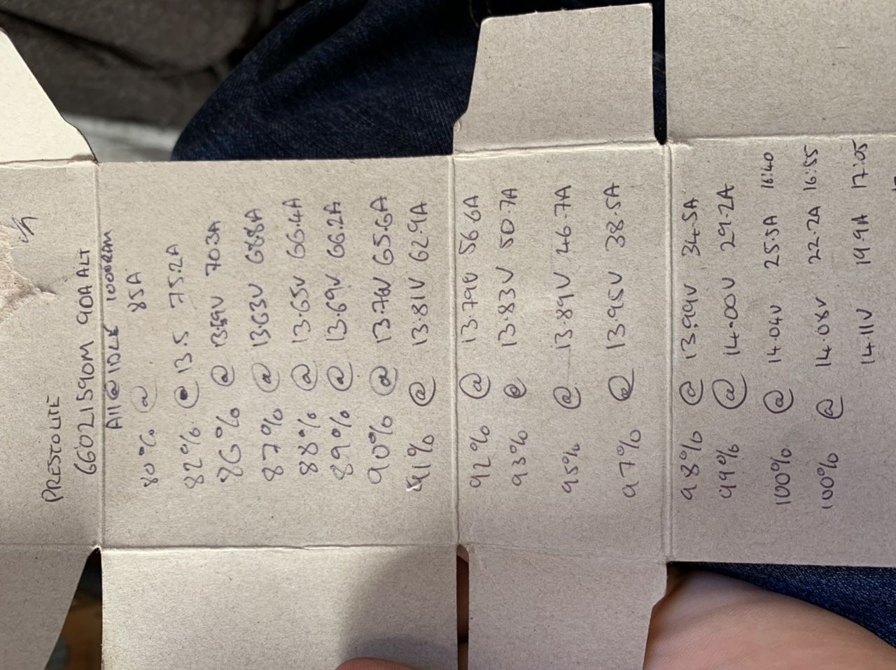
I’m keeping an eye on on it still, the voltage is staying the same and the amps are dropping off. Batteries, err 4x Trojan T105. Can’t remember the capacity of them , 220ah so 440 Scott
-
Well, thank you all who contributed, it has made my day a lot less stressful. I removed the ceramic washer from under the B-, turned the ignition on and the battery aux indicator lit up straight away. results according to my mastervolt monitor: Thank you all ?

-
Running for 10 minutes. Started at 79% 85A now 82% charged and charging at 13.5V & 75.2A
-
This is how people must feel when I explain IT technical issues to them!!
-
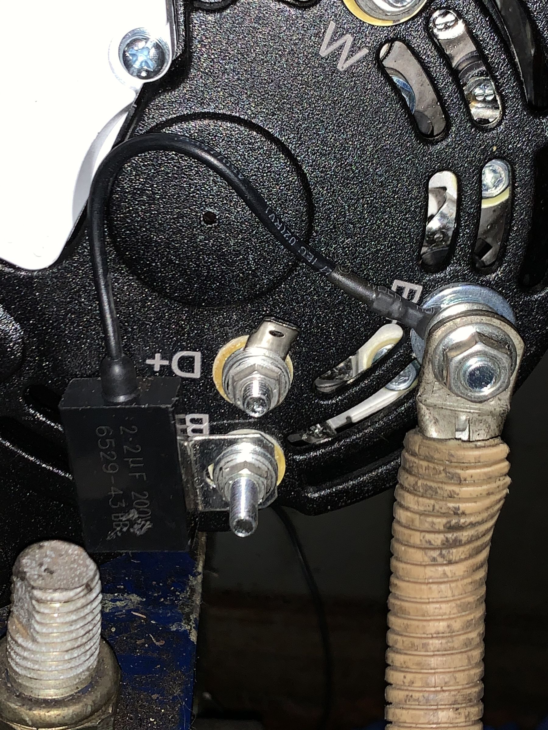
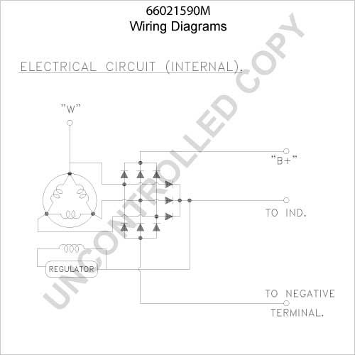
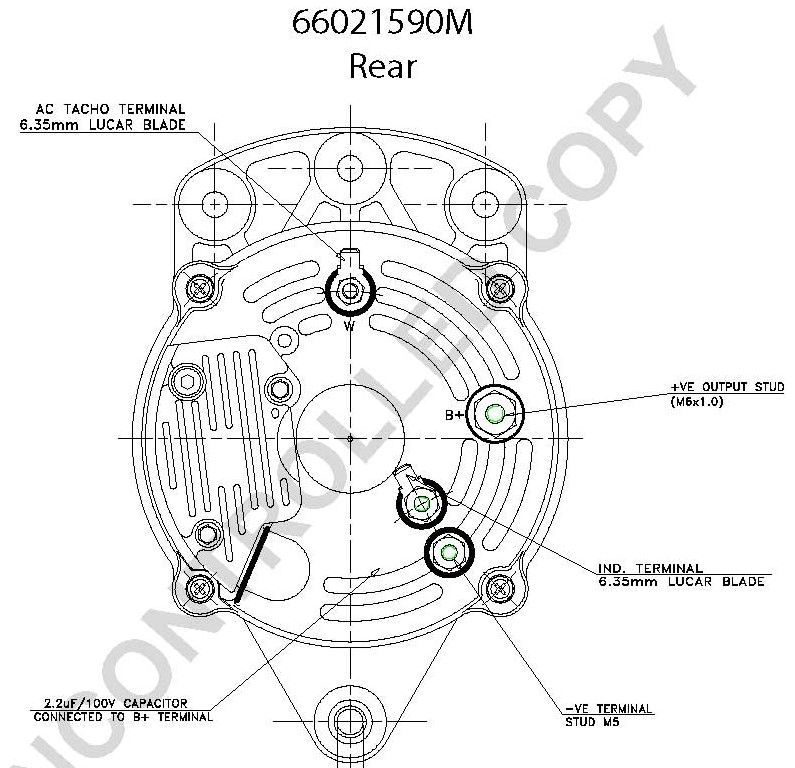
Hopefully last question before the many thanks and documentation reply. The B+ & B- has a 2.2μF capacitor between the connections. Do I leave this in place if I remove the insulator on the B-? thanks, Scott
-
Great, that explains it to me in simplistic terms! I do have ‘spare’ battery connection cables but unsure if I have enough length. Might be tricky to get a cable at the present time in London. and I like your solution Sir Nibble. thank you all!
-
The B- was directly connected to the battery negative terminal. I’m yet to turn the engine over since the drain over night without wanting your advise. The thing that confuses me (not difficult when it comes to boat electrics) the most is the old alternator didn’t have the B negative so just used the mounts as the negative connection and thus the fat cable off the engine?
-
The B+ is a m6 and the B- is an m5.
-
Thanks guys, that’s my view on the B- too. It is only a yellow ring connector so not able to take a massive cable anyway. I’ll check negatives all the way through the circuits (domestic & starter) and I did clean up the pin connector as that has been a pig in the past. I have been draining the domestic batteries down a little just to see what happens in the bulk charge. Scott
-
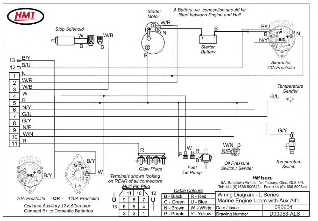
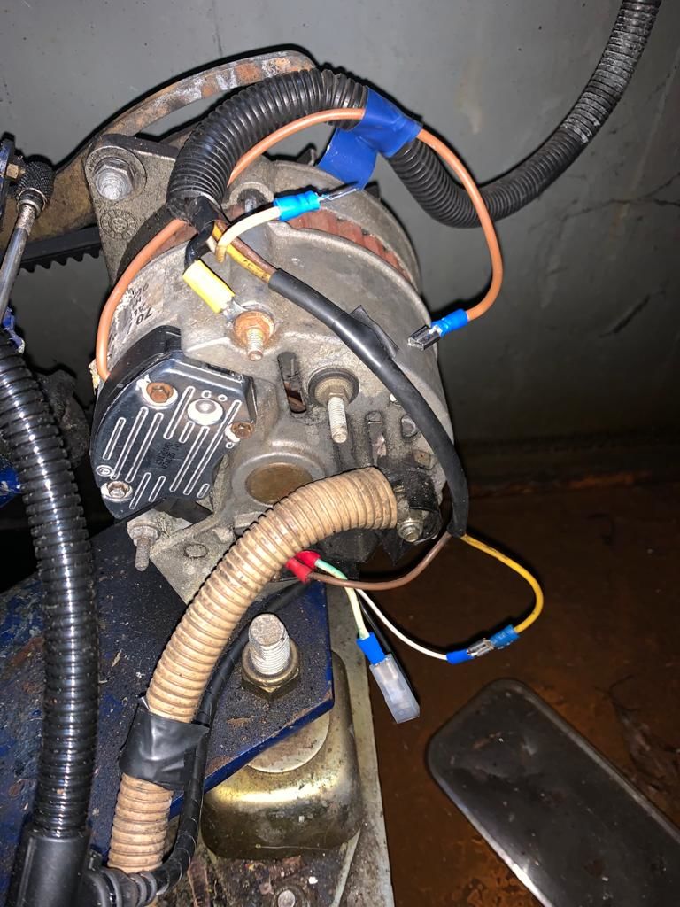
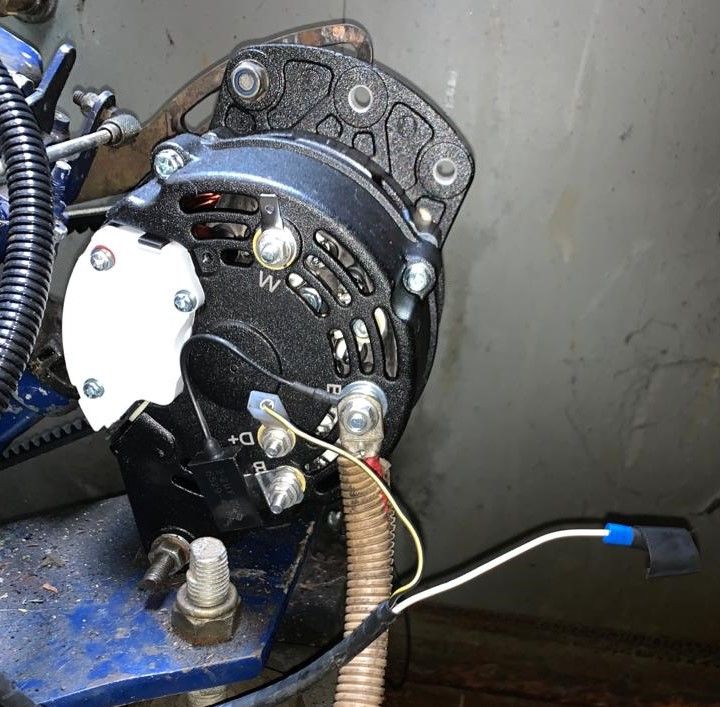
Hi All, I'm after a little advise about my replacement alternator, Pestolite 66021590M, which I have fitted. It is replacing the original 900021-als with is a Lucas a127 70amp which was teamed up with Sterling Advanced Regulator ( the blue one). This is a photo of the old alternator in situ. Looking at the HMI diagram (attached) the old alternator doesn't have a negative connection, so assuming the case was the negative. On installing the new alternator I connected the Black & Yellow cable (D+) which connects to the Aux Light on the control panel and the battery plus (B+). Turning the ignition to the on position the the 'Aux Alternator Charge Light' on the control panel did not illuminate as it normally would so I touched a cable between the battery negative (B-) and the engine casing, instantly the light illuminated indicating to me that i need the negative connection. The next test was to briefly turn the engine over and jump between the B- and the engine casing. No output from the alternator until the jump was made which shot up to 88 Amps and the engine tone changed to indicate a load. Using a bit of 6mm cable I connected the B- to the negative on my batteries using ring connections, I turned the engine over, keeping an eye on the cable temperature, the charge rate was significantly lower about and Amp (forgot to write it down) and with the inverter running the batteries we discharging. The batteries were almost fully charged (~98%) but I would have expected with the inverter & TV one the the charge would have been positive. What am I missing or doing wrong? Also, I am unsure what the negative cable should be, is it just completing the circuit or is it taking a heavy load therefore needing a heavy duty cable? Any views / suggestions / ideas / pointing out my mistakes would be great, Thank you, Scott
-
Just had the same issue, I used a Torque 6 (T6) to get the grub screw out.
-

Eberspacher service in London.
swmenzies replied to oneyedriley's topic in Boat Building & Maintenance
What route did you go down? My one is playing up and now it's approaching winter I would like to have it in fully working order. Many thanks, swmenzies -
Three connections on the negative side: Parallel connection, starter negative and theoretical earth. Three connections on the postive side: Parallel Connection, Inverter and 12v isolator. That now seems odd to have the inverter separate from the isolator, though the inverter does have a 'hard' on/off switch. Need to think about that. I asked a question to my electrician friend and was handed 9inches of 5x25mm copper rod. Fantastic!
-
That's a pretty simple idea, and I like it. I could buy a long bus bar and chop it in half so I've got all the right nuts and bolts too. My only thought, is that I really don't know what sort of size to get as they all come with different Amp ratings. I had a look at those but wasn't sure about the negative terminal
-
I got the batteries installed without shocking myself or blowing any equipment. One thing I had not considered when buying the batteries was the terminal height, on one of the positive and negative connections I had three lug connections which was too tall for the nut to grip the thread. Thankfully I had a number of post to thread connections but they needed opening out to fit around the larger/wider post bottoms (see image 1.), this however is defiantly not ideal as the post height (below the screw thread) is not full height. This leads me to my question, can anyone recommend a solution to my problem? Looking on the internet I found a couple ideas but not a real solution. Image two, multiple connections for large lugs and smaller connections for voltmeters/ammeters the problem with that is the post connection. Image three is technically viable (so I believe), I can put one or two lugs on the terminal, pin down the extension with the lugs and the nut then put the remainder of the wires onto the additional threaded connection, the real problem is that I cannot find a UK/European supplier. I guess the correct solution would be to install high current bus bars, I am a little resistant to this idea as this would mean making big changes to the wiring and the battery box. Many thanks, Scott
-
My batteries have arrived and so have the cables, I've got some work to do this week end!
-
Yes, very good point! Thanks
-
So lets assume it's either 50mm² or 70mm², what effect could this have if I used one thickness to join the leisure batteries in series & parallel and one thickness for the starter battery?
-
I measured the thickness of the cable to be 18mm inc. sheath, would that be 70mm² cable?
-
Did you crimp your own cables? or did you buy them pre made?
-
I'm going to bite the bullet and get the Trojan T105s, this is going to take a little re-jigging of my cabling. I have read that all the terminal cables should be equal in length (parallel), does this apply to the interconnecting (series) cables? Can the two series cables be of the same length but different to the parallel connections?
-
I'm very impressed, that's a pretty ingenious set-up
-
Got space for four leisure batteries (330L x 172W x 242H) The HydroLink would solve the height issue and straddling the engine (Cruiser stern!), though I couldn't find anywhere in the UK that sells it.
-
So if they fit, four of them @ £99 each could be a good solution
-
Those T105s are pretty tall at 276mm!