

Giant
-
Posts
667 -
Joined
-
Last visited
Content Type
Profiles
Forums
Events
Gallery
Blogs
Store
Everything posted by Giant
-
We've got basic Clarke one from Machine Mart which has lasted for years with no problems.
-
Would be good practice to put an elbow piece on that conduit where the flex goes up into the garage unit. You'd be surprised how easily water will dribble down the box, along the flex and all the way through the conduit to drip out of the other end.
-
Your diagram doesn't show any earth-neutral bond for the inverter. Also do you really need separate 16A/32A hookup and a changeover switch? If you want to support both you could just have a 32A hookup, 32A cable, and an adapter you can plug in at the bollard end when you need to use a 16A supply. That said, 32A supplies at visitor moorings are pretty rare so unless you have 32A at your home mooring, you're unlikely to ever need a 32A hookup.
-
Just to be clear on the actual limitations around London - at 2.75m your air draft would be about the same as ours. You would not be able to get up the Lea beyond the A104 bridge in Hackney, and that cuts off one of the main routes for London cruising. I don't know about the canals as we're too wide for those anyway, but a glance at Canalplan suggests you'd not even get to Uxbridge on the Grand Union - you'd be stuck at the bridge by Packet Boat marina. Plenty of leisure cruising to be had for a big boat on the Thames, the Medway and around the estuary, but with a boat like that you can't do the "continuous cruising" thing round here.
-
Sorry, I think I have got this wrong. I thought the 2R and 3R were the 2:1 and 3:1 versions but I see now that all JP reduction boxes are 3R regardless of ratio. So I'm not sure if this one is a 3:1 or 2:1 now. Unless someone can tell from the photos, I'll turn it over to check.
-
Hi Admiral, We might be able to do the swap you're looking for. We are currently stripping down a 1952 JP3M that came with a 3R box on it, but the one in our boat is a 2R, so a spare for that would suit us better. See photos below. The engine was supposedly taken out of a barge in running condition a few years ago. We haven't found anything that suggests otherwise, but we bought it as-is and are stripping down to check everything properly. We haven't had the box off the engine yet but that's probably one of the next jobs. We're in east London. PM me if you're interested.

-
Right. This project was on hold over the spring and summer while we focused on paint and varnish but now that winter has set in we are picking it up again. We have also moved engine #2 closer to home so it is now much easier to go and work on. We never did succeed in getting the other two valve rocker shafts out, but we were given a great tip by Steve Waddington over the summer when we stopped by at the yard at Swinton - how to take a JP head off without needing to extract the rocker shaft!: Pick one of the valves. Turn over to a position where the cam for that valve is not pushing on the follower, and the piston is well clear of the valve. Lean really hard on the top of the valve side of the rocker to fully compress the valve spring, thus lifting the other end of the rocker up. Keep leaning while you: Extract the pushrod, which will now just fit past the rocker. Sneak your 3/4" Whitworth socket (which will also just fit past the rocker, if it's the right sort) onto the nut on the tubular stud. Attach a socket drive extender, which will end up sort of jammed up against the rocker. Gently release the valve spring. Now you can unscrew the nut with the rocker and shaft still in place! Simple in retrospect but would never have occured to me, and I'd never heard of this trick. So thanks to this, and a gudgeon puller I made up, I have now got the other two heads off and their pistons and con rods out. I have measured the remaining two crank journals and they match the first one we looked at: pretty much exactly 20 thou under 3". So that seems to support the previous theory that this crankshaft was already ground to 0.020" undersize and has seen very little wear since. The surfaces of the big end bearing shells look okay but there are some dings and chips around the edges of a couple, and around the oil hole in one of them, so I'm guessing those will want replacing. Now pondering what to take apart next, and worried about any pitfalls in doing so. About the only easy looking thing left to come off is the water pump. Then I suppose getting the gearbox off, which I'd like some tips on, as that's heavy and seems like it must need careful support as it comes off the end of the shaft. After that we must be into territory where we need to borrow a hydraulic puller, for the flywheel and cylinder liners? Tips and pointers welcome - we've not been this deep in one before.
-
These days, the entire world probably would, because of the high chance someone nearby would have a phone handy to video it. Longer ago, all you'd have is some bloke down the pub swearing blind that he saw a plane fly under the bridge, and his mates rolling their eyes and saying pull the other one. Meanwhile, in a flying club bar somewhere, the truth of the tale is told in whispered tones, known to all the local hooligans but never mentioned in earshot of the CFI, passed down quietly through the years... I know a good few such tales, and I ain't tellin'.
-
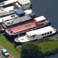
At a guess I would say that these are dumb vessels built for towing, rather than sailing keels that have been de-rigged. But I stress that's a guess - I really don't know the wooden era craft well. I would have thought the lack of the characteristic bulwarks and hawse holes at the bows, or the rather diminuitive feature in place on Ravensthorpe, should be a giveaway for someone who knows their stuff. The style does look fairly consistent with other barges from the Calder & Hebble, e.g. these pictures of boats built at Mirfield, taken from this website: Do you know about the humber barges group on facebook? I would try there.
-
Sorry Phil, I think I managed to completely skip over that sentence in your original post. I think you're on the right lines there. As to paint though, you want to get the best possible protection on there while you have the chance, as it will be a huge pain to get at once the floor is in and everything on top. I would be going for a good quality two pack epoxy and nothing less.
-
Not a lot to go on for location, but the name Ravensthorpe is legible on the leftmost one.
-
There is some logic to isolating the bilge space from the cabin - doing so keeps cold air from the bilge reaching the cabin, and wet air from the cabin reaching the bilge. Shutting it off too completely is not smart, though. You need some ventilation of the bilge space to dissipate moisture that does get in there, whether by spills or condensation or leakage of wet air from the cabin. Otherwise moisture will accumulate. The smart way I've seen this done is to have ventilation ducts running up from the bilge space at both ends of the boat, opening directly to the outside, with no connection to the cabin. A small 12V fan at one end will help to gently circulate air with negligible power consumption. This is especially important if the bilge space is very shallow as it will be in a narrowboat.
-
This is a common misconception. I recently had to survey marine insurers on this issue and found that almost all include wreck removal cover as standard on their basic third party policies. That included at least: Towergate, Euromarine, Basic Boat, Navigators & General, and GJW. Haven Knox-Johnston had it as an option.
-
In the current basic Fischer Panda model it looks like the alternator has no grille open to the inside of the cocoon at all. The cocoon is sealed apart from a small intake box at one end which leads directly into the alternator housing, which is sealed too. The air cools the alternator then continues into the engine intake through more closed pipework.
-
But that doesn't have to come from ambient air in the casing. It can come in to the engine through an intake port that's isolated from the rest of the capsule, just like the exhaust is on the way out.
-
The key difference is water cooling. If you're relying on air cooling then there's a limit to how quiet you can make the thing, because you can't really allow airflow through the casing without also allowing a lot of sound out. If everything is water cooled then the casing can be pretty much completely sealed. Note that this includes water cooling of the generator coils, not just the engine.
-
 For those fretting about the word "deconstruction", it is a standard term used by National Historic Ships and they publish a whole book about it, Deconstructing Historic Vessels, available as a free PDF from them here. It accompanies two others on Recording Historic Vessels and Conserving Historic Vessels, collectively intended to advise best practices for conserving vessels or, when that is not possible, recording them and making appropriate plans for disassembly and preservation or reuse of parts - exactly the considerations people are discussing in this thread. CRT's use of the term would suggest to me that they have this advice in mind.
 -
It's not really necessary to be able to adjust the pressure output, you normally have an adjustable nozzle that can vary from a tight jet to a wide fan. The distance you hold the nozzle from the surface also makes a big difference - the closer you get, the more aggressive it is. I find this gives plenty of control. You do need to be careful though, even on good paintwork it's possible to damage the paint if you go at it too hard with a tight spray close in. Personally I find ours useful for a quick, low-effort wash down, but it won't shift everything, and you get a fair bit of backspray of dirty water over other surfaces nearby, so you need to plan your approach and rinse off afterwards.
-
Surveyor recommendations in London
Giant replied to Alethea Price's topic in Boat Building & Maintenance
This is sounding an awful lot of alarm bells to me. Rejected by a previous buyer post-survey, known to need welding, and the seller is acting shady? Why this boat? Plenty on the market. If it's because it's cheap, it's very probably a false economy. -
Having just spent the last couple of days sanding down our iroko wheelhouse, I am going to vote for this bit being iroko as it looks awfully similar now you've sanded it. I have some bits of teak sitting around too but the grain looks quite different. Lovely bit of wood either way.
-
That's great news Joe. Any word on how they came to change their minds?
-
Bear in mind that the same insurer may be able to offer different options for cruising area limits, on the same base policy. We are with Towergate and they gave us an unrestricted "coastal and inland waters of the UK" on the schedule. (We're a high-sided barge with a home mooring beyond the Thames Barrier). Call each insurer and ask what their options are.
-
Builder's plates from John Harker Ltd, Knottingley
Giant replied to Giant's topic in History & Heritage
Just to clarify on the methods: When I started this project, I only had a printed copy of a brass rubbing to work from - I thought the original would have been a thick cast brass piece, like the plates I'd seen from Dunstons of Thorne. With that in mind I made a laser cut plastic master (post #11). Then I saw Andy Horn's photo (post #16) which made it clear the original was engraved in thin sheet brass. The final piece is not laser cut, but engraved with a CNC router. The delay has been getting this working properly! This is the job in progress:
-
Builder's plates from John Harker Ltd, Knottingley
Giant replied to Giant's topic in History & Heritage
Wasn't present in the 1948 one I traced the design from :-P -
Builder's plates from John Harker Ltd, Knottingley
Giant replied to Giant's topic in History & Heritage
Finally finished this!


