

Giant
-
Posts
667 -
Joined
-
Last visited
Content Type
Profiles
Forums
Events
Gallery
Blogs
Store
Posts posted by Giant
-
-
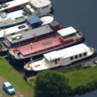
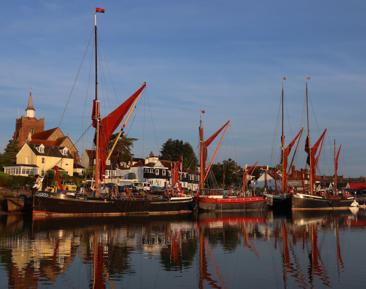
Bit out of the way for most boaters on here, but Maldon is gorgeous right now.

-
 3
3
-
-
3 minutes ago, Steve56 said:
Make sure the replacement comes with a pulley as they are not interchangeable.
Yes, the guy fitted it up to match the one I brought in so should be all good to go.
-
Success - have now traded in the failed one for a shiny new A127.
-
1
-
-
Thanks for the leads. Have found a similar specialist in Bexley so I'm pulling it out and taking it over there this afternoon.
-
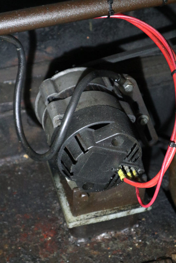
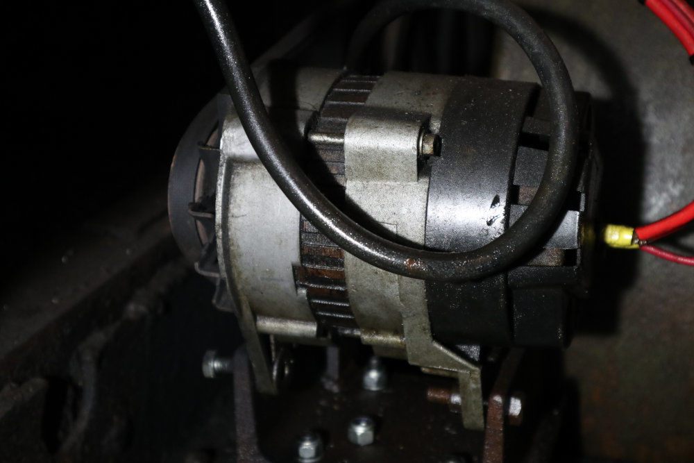
Our alternator has failed. No markings on it. Design looks like a Lucas ACR but the back cover doesn't exactly match any of the variants of that I'm seeing online.
We very badly need to be back underway on Thursday with a working alternator, so I want to find a drop-in replacement for this by the end of tomorrow.
We're tied up at Gravesend. There is a Euro Car Parts here but they don't seem to deal in anything that old. I can travel tomorrow to anywhere in or near London to pick one up.
Next day delivery could work in theory (we have an address nearby), but has been very unreliable lately so would want to be very sure the supplier could get it done.
Any ideas?
Photos:
Symptoms:
Was working fine when we left, 13.8V at idle and 14.4V with some revs on.
At some point I noticed the battery voltage dropping, went below and found the alternator light on despite plenty of revs.
Battery and field coil connections are fine.
There's about 2.3V between negative and the field coil terminal regardless of revs (rest of the battery voltage is dropped in the bulb).
The belt had got a bit loose so suspected that, but have now tightened it and no improvement. No squeaking.
Diagnosis:
My understanding is that this means either the brushes or some of the diodes have gone. Fixable but given time constraints we want to just swap it out.
Installation:
16" pulley on the front of a JP3 driving a 2.5" pulley on the alternator, so ~7700rpm at full revs (1200rpm engine). V-belt with "A" section. Turns clockwise looking from the pulley end.
-
On 30/08/2020 at 17:44, Alan de Enfield said:
They do a 6 step and a 9 step version.
Without getting it out of the locker I'd guess 12" apart.
I have 6' of freeboard and have 3 steps in the water.
Thanks. Our freeboard is about the same so I'll keep an eye out for the 9 step version.
-
I like the look of those ladders at the start of the thread, hadn't seen that design before - will have to keep an eye out on ebay for them. @Alan de Enfield or @magnetman, how far apart are the steps on yours? I want to work out how many steps we'd need to get.
-
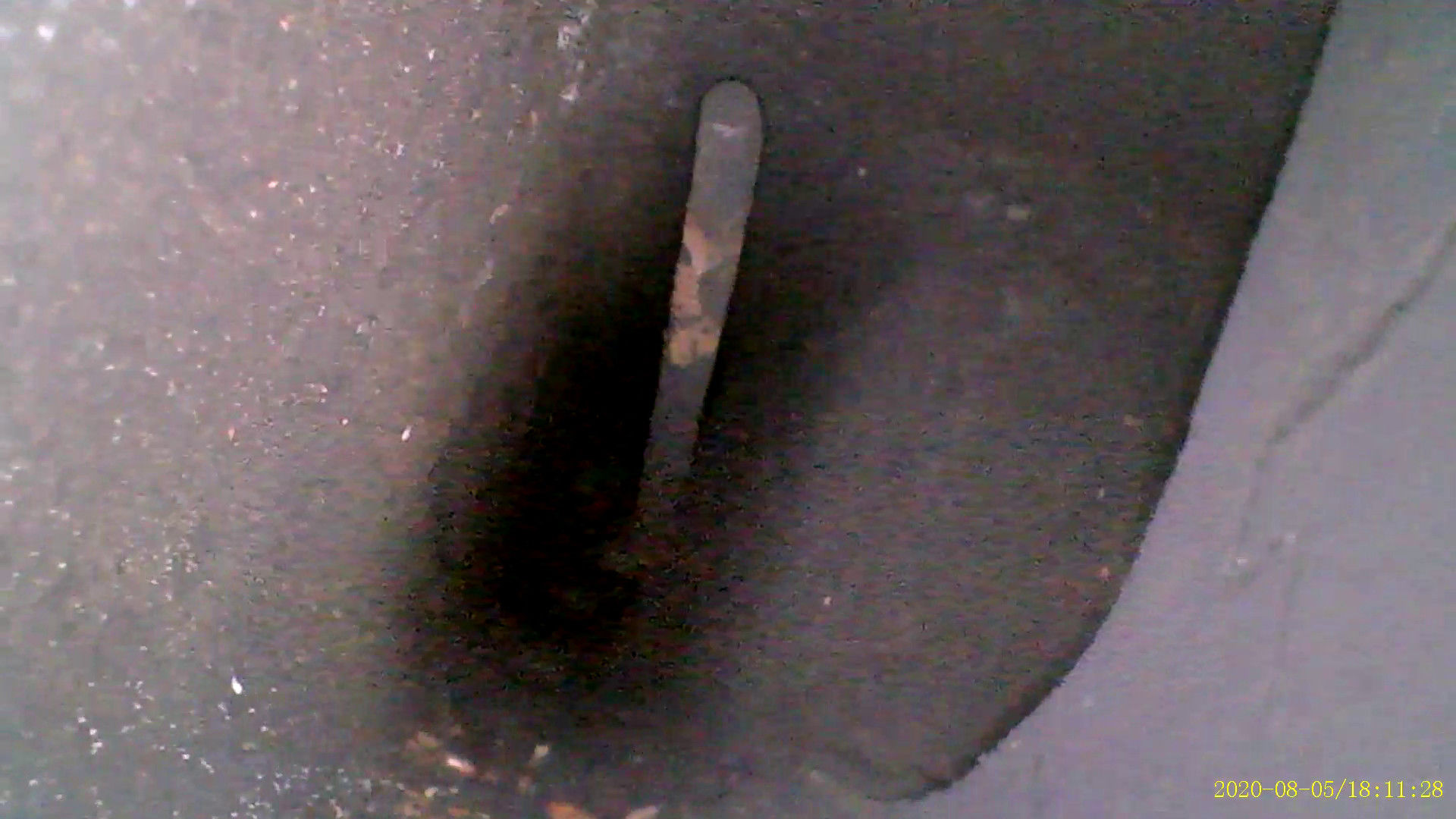
Today's mystery, however, is in the exhaust manifold that came off engine #2. We'd like to use this one, because the troublesome joint to the silencer is in much better shape. But while having a look through the channels in it yesterday, I found this inside the exhaust - a bent rod around 3-4mm in diameter. I could just about reach each end of it with a finger, through the forward two exhaust ports:
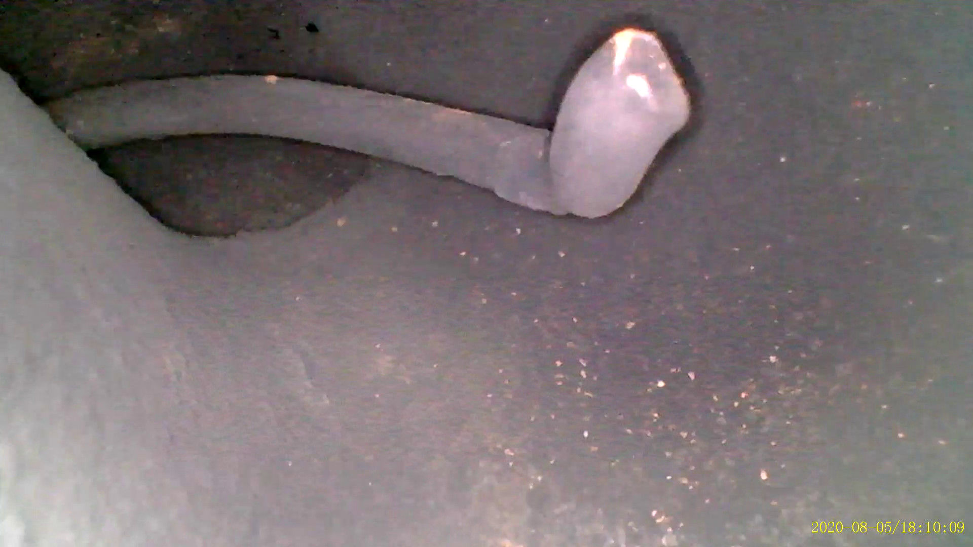
At first I thought it was just lodged in by being bent around the corner, and tried to free it, but eventually I realised that both ends were free, and that all I was doing was bending it around a point in the middle where it was welded to the casting - here, you can see where the weld is and where I've dislodged the carbon either side by bending it:
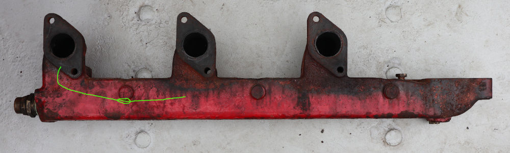
So it seems like this is a brass brazing/welding rod that's been used to fix a hole at that spot, and then left in there. For context, it's positioned like this (in green) within the manifold, with the weld (circled) seeming like it's on the edge of that round feature on the side of the casting.
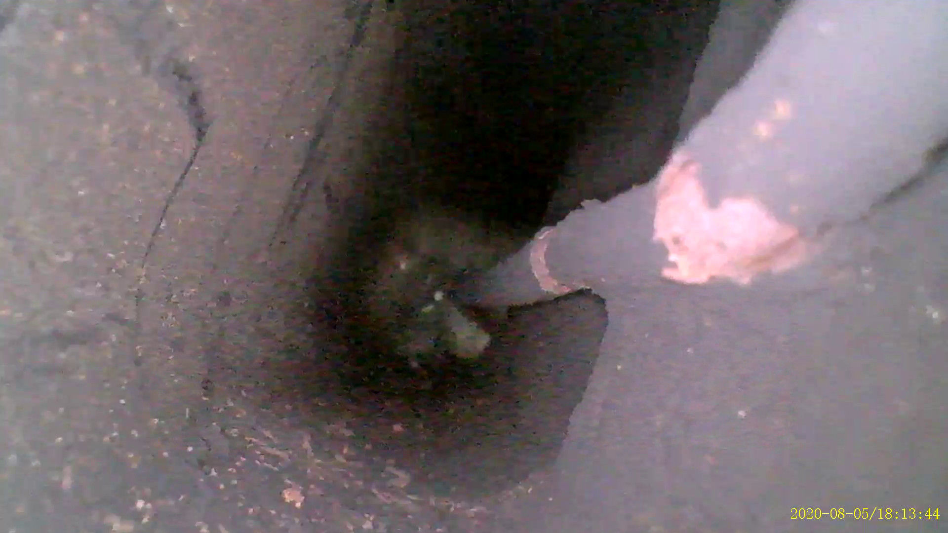
It seems like that round feature is at the end of a boss, that shows up as a ridge across the exhaust channel. But it doesn't seem to be a tube that connects to the water side of the manifold, and it would make no sense to have a tube across there - the water flows along the manifold below and to the side of the exhaust channel.
So why was it necessary to weld up at this point? Any ideas what's gone on here?
-
Well, I suppose we should start updating this thread again.
The bottom end & gearbox of engine #2 have been with @RLWP and @Mrs Tawny Owl for a while now getting a complete strip down & rebuild. The crank has been reground, reinstalled on new main bearings and everything is looking very shiny.
Sometime soon, we will be taking the boat into to drydock, and while we're there we'll have engine #1 craned out through the deck, and the newly rebuilt bottom end of engine #2 installed in its place, after taking the opportunity to strip the area under it back to bare metal and repaint. Then we'll be rebuilding the top end onto that, with a mix of parts from engines #1 and #2.
There's a complicating factor with the reduction boxes, because the one from engine #2 was water damaged and unusable, and it's not possible to remove & strip down the installed one until we have the engine out. So we're going to need to get that apart, deal with any issues and get some paint on it before reinstalling. We're hoping there's not too much wrong there - it runs smoothly, and looks to be in reasonable condition on the inside as seen by an endoscope down the dipstick hole.
Meanwhile, we've been getting engine #1 as ready as we can for its final voyage, swapping in some top end parts from #2 that are in better shape, and installing some new bits, all of which will then get transferred to the newly rebuilt bottom end.
-
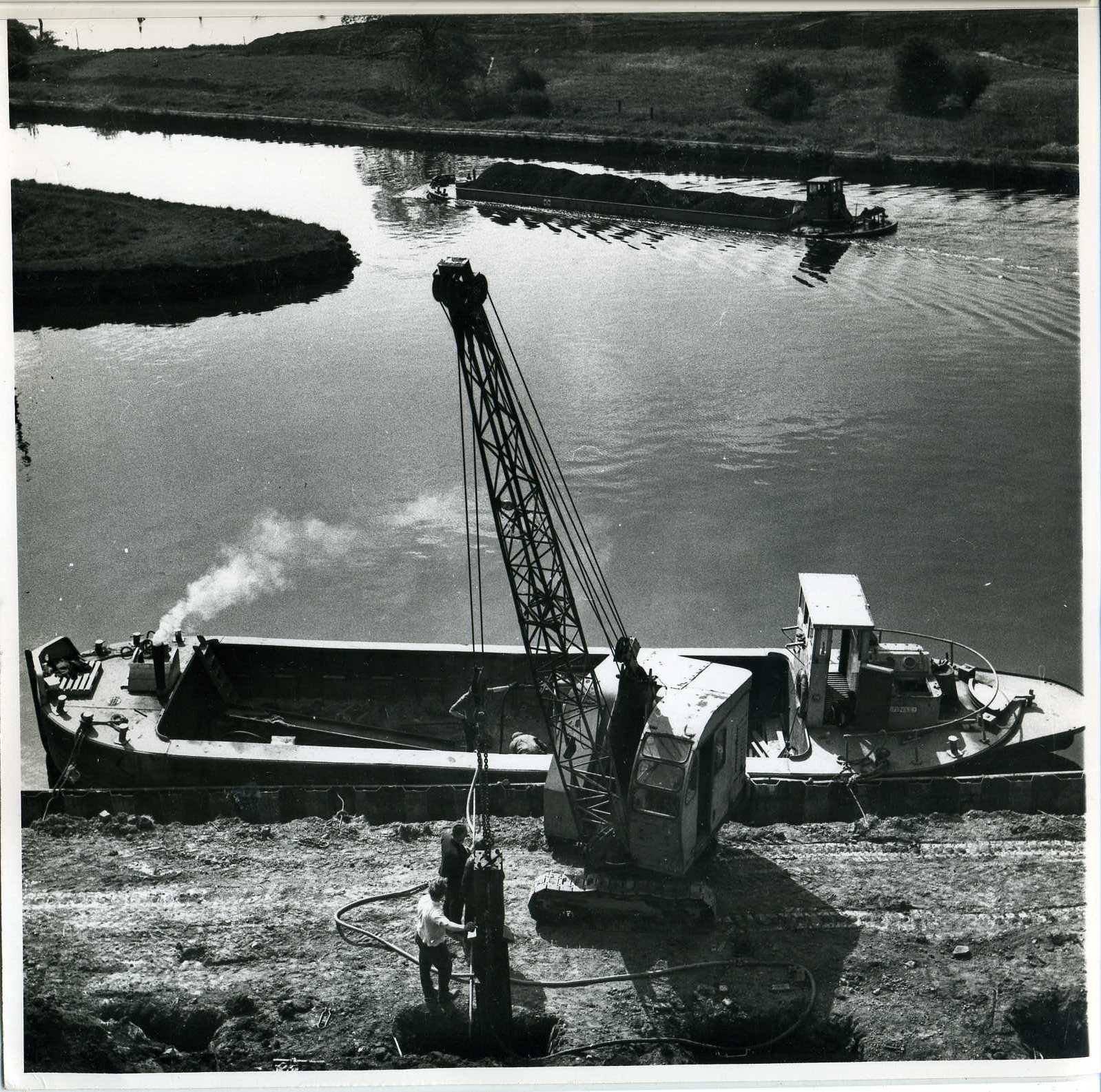
She was the last built of a set of four, her sister ships are Barnsley, Haddlesey, and Knottingley. All were dumb barges originally, Knottingley and Stanley were motorised later.
I think this is her in British Waterways colours - it's a still from 3:41 into this amateur film in the BFI archive from 1960.

This might be her too, or one of her sisters:
This is her sister ship Knottingley from a recent ad:
Look for a Facebook group called "Barges tugs and workboats on Humber" and ask around on there, it's a treasure trove.
-
Looking good Simon. Need to find some more time for our JP3M project...
-
1 hour ago, Boater Sam said:
May well mould some new ones, would Shore hardness 85A be best or a softer 70A? There seems to be some guys on here who know their rubbers.
If I had the original in my hand I could give you a rough guess what it is. The proper tool to measure is a durometer, but a useful rough guide to Shore A hardness is:
20 = Rubber Band
40 = Pencil Eraser
60 = Car Tire Tread
70 = Running Shoe Sole
80 = Leather Belt
100 = Shopping Cart WheelI would go for 85, given that you'll be putting your weight on them when you sit on the seat and presumably they're not that big. Think about a running shoe sole being 70, and you spread your weight across the whole foot on that.
-
2 hours ago, WotEver said:
It’s probably something which could be cheaply 3D printed (many local printing companies offer 3D printing as a service). The biggest problem would be in getting the computer model designed.
Yeah, a 3D print in Ninjaflex or similar rubbery filament is another option, but I'd hesitate to use a 3D print in this application since the surface will be rough and somewhat porous, which makes it hard to keep clean. And with the flexible filaments you can't really smooth the print with sanding or with solvent vapour in the same way as you can with solid plastic.
-
If you have an original one as a reference - even if in poor condition - then it's possible to cast a mould from it, clean it up, and use a two-part liquid casting rubber to make new ones. I do a bit of this sort of process for making prototypes of plastic parts etc.
-
3 hours ago, Peter X said:
You could get it into river estuaries, e.g. as far as the Pool of London
Where you might cause some amusing confusion as there's already one Golden Hind replica in Southwark.
-
Although not the same issue, a group it might be worth talking to for general advice on persuading the MCA to accept something unusual would be the Sea Change Sailing Trust based in Maldon. They are currently building (edit: in steel) a brand new Thames sailing barge to carry cargo under pure sail - no auxillary engine at all. I gather that, as you might imagine, this has involved some rather interesting discussions with the MCA.
-
I asked the Humber barges group on FB and none of the ex-bargemen there had heard of an ATIN... but there was a Sheffield size called NITA, owned by J J Tomlinsons.
So it looks like our intrepid photoshopper flipped a photo of NITA to get a more visually convincing result... and then flipped the resulting И to get ATIN!
-
1
-
-
Just to confirm your intuitions - that is definitely a Sheffield size motor keel, and the waterline on the bow corresponds to the 7ft draft mark on ours.
The next question though is whether the name has also been doctored. I have never heard of one called ATIN and can find no mention of it.
-
24 minutes ago, WotEver said:
That’s just the sender though. You then need the matching gauge.
Indeed - also true of the Vetus ones posted above.
24 minutes ago, PaulJ said:Im afraid you are wrong there. The last loo I repaired had one sitting on top of the tank-If memory serves me right it was a Tecma -it was part of the standard flush/tank level panel
Similar idea- https://www.thetfordmarine.com/product/field-effect-sensor/
The Vetus one you posted first does need a hole. I'm familiar with them - I used one to replace a faulty mechanical one on the black tank of a tall ship I help out with. It was a drop-in replacement using the same SAE 5-hole mounting but still needs the cutout to look through. The BEP is similar.
The Tecma field effect sensors will work through a plastic tank but won't drive an actual gauge - they just tell you when the level has reached the height of the single sensor.
The Gobius unit does drive a gauge without needing a hole, but it's not an ultrasound unit - it's just just three field effect sensors used together. So it can distinguish between empty, above first/second/third sensor - driving a coarse LED gauge indicating in quarters - but won't give you any finer resolution than that as an ultrasound gauge would.
I stand by my advice that an ultrasound one, driving a gauge, as the OP asked about, requires a cutout.
-
1 hour ago, RichLech said:
I've seen reference to tank gauges that use ultrasound to measure the level, through sensors stuck on the outside of the tank.
They go on the outside of the tank, but you still need to drill a hole for them to look through and some screw holes for mounting. Same as you would for a mechanical float based one like the Wema/KUS units.
There is a BEP one which is slightly cheaper than the Vetus: http://www.cactusnav.com/ultrasonic-tank-sender-p-15649.html
-
1 hour ago, smileypete said:
If you want wide angle, why use spots? (rhetorical question
) Maybe bypass the MR11s and go for LED strip, puck lights, or even MR16s.
For large boats I wonder if it's better to have the lighting done in mains via a small dedicated inverter, as there's a very wide choice of GU10s.
I have a few dimmable Philips GU10s LEDs that are 'all glass' and I wonder if they do without electrolytics, some of the MR11s on ali look the same, but it's a moot point if wide angle is a must.
If we were starting from scratch I might indeed do it differently. However with 20 MR11 fittings already neatly in place, I was hoping to just get some bulbs that worked rather than yet another project...
-
1 hour ago, WotEver said:
So bearing in mind that...
Why don’t you simply do so with the failing ones?
I am leaning in that direction, the problem is that it's impossible to get them open without breakage. The diffuser on the front is frosted glass, which has been epoxied in to the plastic housing.
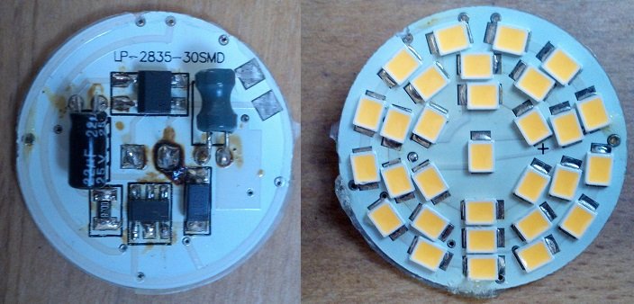
I have destructively dismantled a dud one and extracted the board:
The design itself doesn't seem to be that bad. My guess is it has just been let down on lifetime, like so many products, by an overstressed electrolytic capacitor.
I have identified all the parts except the unmarked inductor - the driver is a PowTech PT4115 which should be more than adequate, with a Vishay MB6S rectifier and that 22uF cap in front of it to handle AC input (unnecessary in this installation). The diode in the step-down circuit is a Vishay SS14.
The bulb does run pretty warm. The ICs should be fine with that, but I would guess that the cap has failed from running at high temperature several hours a day for a year. It's labelled as rated to 105C, but as noted in this excellent app note from Maxim about caps in LED bulbs, that probably means it's only good to a couple thousand hours at that temperature, even assuming its ratings were verifiable in the first place. The capacitor is marked Jakec, who I don't know, but the first hit for "jakec capacitor" on Google is someone on badcaps.net saying they're crap...
So I would guess that I could fix these by just replacing the capacitors, if I could just get the casings apart without breaking them!
-
3 hours ago, smileypete said:
How about buy one or two of a few different ones from Aliexpress (usually the cheapest source), reverse engineer them, let us know what you think.
Personally I would look at the 'COB' ones first and foremost... eg:
ETA: The best for a mainstream brand at typical high street prices may be the OSRAM Star MR11 3.7w (345lm) for £9.99:
https://www.clasohlson.com/uk/Osram-GU4-(MR11)-LED-Bulb/36-6918
The second set of Chinese ones we tried were "COB", this style, but weren't that exact seller.
The problem with both those and the Osram ones is the narrow 35 degree beam. We've been much happier with the wide angle 120 degree ones which end up lighting the whole area rather than just the spot beneath them.
-
We have been struggling to find 12V MR11 LED bulbs that both suit our preferences and are reliable.
We've been through two sets I picked out from Chinese suppliers, the first set were a bit dim and too blue for us, the second set were brighter and warmer but too narrow-beamed and started failing after a few months.
We thought we'd finally hit the jackpot with these ones from UltraLEDs:
They're seriously bright (30 2835 LEDs, 350 lumen), warm colour temperature, and have a nice wide 120 degree spread with a diffuser on the front rather than just an exposed PCB with the LEDs on.
Having spent a bunch on getting 20 of them, I stuck a 12V regulator in the lighting circuit to protect them as it wasn't clear if they'd be OK with straight battery voltage.
All looked good but a year or so on more and more individual ones are starting to flicker - seems to be premature degradation of the internal drive circuitry, not the LEDs themselves. We're now losing more of them by the day and going to have to replace yet again.
Any ideas? These latest ones were perfect aside from the short lifetime. I have looked at Bedazzled etc but not turning up any as bright as this, their best MR11 is 18 2835 LEDs at 230 lumens.
I design electronics so would happily even make my own ones with decent drive circuits! But would need a source of MR11 housings and diffusers.


Treating black rust on the inside of a heavily pitted bilge.
in Boat Building & Maintenance
Posted
It wouldn't be impossible to get it blasted. You'd need to put up some plastic sheeting around the rest of the area, wrap up that propshaft, remove anything that can be got out of the way, and shovel out & hoover up all the grit when finished.
If you can get good epoxy onto freshly blasted steel and follow it up with a couple more coats you will never have to worry about it again, it will outlive you. The epoxy works its way into all the microscopic nooks and crannies of the rough surface. The result is an astoundingly strong bond, you're basically making a thin layer of composite. You'll never get the paint off except by abrading it away.
Alternatively, do the same thing you did before but without the Vactan. By the time you've got to a surface that's been needled and gone over with a wire wheel, you shouldn't need a rust converter. Anything you have to put on and rinse off at that stage is probably just going to worsen adhesion of the epoxy.
The Clarke needlegun isn't bad, but for pitted areas it's often necessary to take the needle attachment off it and use the single-point chisel that comes with it instead. It's much better at knocking those last bits of black magnetite out of the bottoms of all the pits. The needles can often fail to get right in there, since too much of the available force is hitting the surrounding areas instead. For an area that gets wet, it's crucial that you get right down to sound metal in every pit, or there's bound to be water trapped between layers at the bottom of them.