seasurveys
-
Posts
31 -
Joined
-
Last visited
Content Type
Profiles
Forums
Events
Gallery
Blogs
Store
Everything posted by seasurveys
-
Did find that as well and contacted the seller. Exactly the same basic pump but the pulley is an interference fit and not compatible as the V is too close to the body by about 2" and the shaft end is not compatible with the existing pulley. Took a chance and ordered bearings from Ashley Power in Poole on 1 day delivery. Simple generic sealed bearings imperial. Sent to Yarmouth IOW and fitted them myself aboard with a few tools. Pump fitted back and engine back in commission. Thanks for your help all. John
-
Thanks...think I have traced the bearings. Seal...think I'll have to use the old seal which seems serviceable as never going to find one of those in short time. Even if it leaks a bit the bearings are sealed and just topping up is a much best scenario than no engine at all. Bearings are 1 9/16" X 5/8" X 7/16". On order from Ashley Bearings in Poole and in stock arriving Monday hopefully. So grateful to you all. John
-
ByThat is all very useful . Thanks. Managed to get bearings out on board and they are simple sealed bearings. Not very big. About 5/8 shaft..1.5 inch outer and about 3/8" width. Not exact as no accurate micrometer. Anyone know the exact size so I can order a pair. Obviously imperial...
-
Thanks all. Locked in in Yarmouth IOW and without engine cannot get back to Poole. As said earlier, if anyone has a pump then do let me know. But in mean time will contact the people suggested. Thanks again. John ByThat is all very useful . Thanks. Managed to get bearings out on board and they are simple sealed bearings. Not very big. About 5/8 shaft..1.5 inch outer and about 3/8" width. Not exact as no accurate micrometer. Anyone know the exact size so I can order a pair. Obviously imperial...
-
Thanks all. Locked in in Yarmouth IOW and without engine cannot get back to Poole. As said earlier, if anyone has a pump then do let me know. But in mean time will contact the people suggested. Thanks again. John
-
Does anyone know of a water pump for a BMC 2.2 diesel Commander. Stuck on a boat with water pump failure and unable to get back to home harbour. This is the circulating pump. New or used..doesn't matter. Urgent! John

-
Thanks Tony. Left it with some penetrating oil yesterday so who knows but if that does not work I'll try the mid acid. I might have to figure out a way of supporting the engine/gearbox whilst removing the bracket from the engine. Trouble is the weight is quite substantial & it means probably fabricating something to rest on the bearers and sling under the gearbox in the meantime. There are more difficult problems in the world so I will sort it eventually. Thanks for your advice. Just in case you ever need the favour returned in an area that you might not be fully familiar with, this is my website. www,seasurveys.co,.uk . The engine is fitted in the boat Dalrymple on the right hand column so you know the type of boat John
-
Thanks Tony, your information is of enormous value, particularly the diagram. I will try creating a sealed bath around the core & filling with a mild acid (used phosphoric for a few hours but was reticent to experiment further as I did not know which part should be freed off.) This time I will leave for a day or two before getting more brutal with it. Thanks again John
-
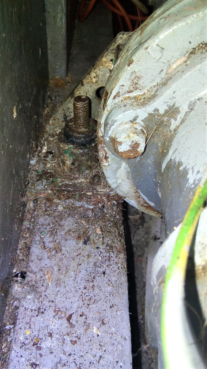
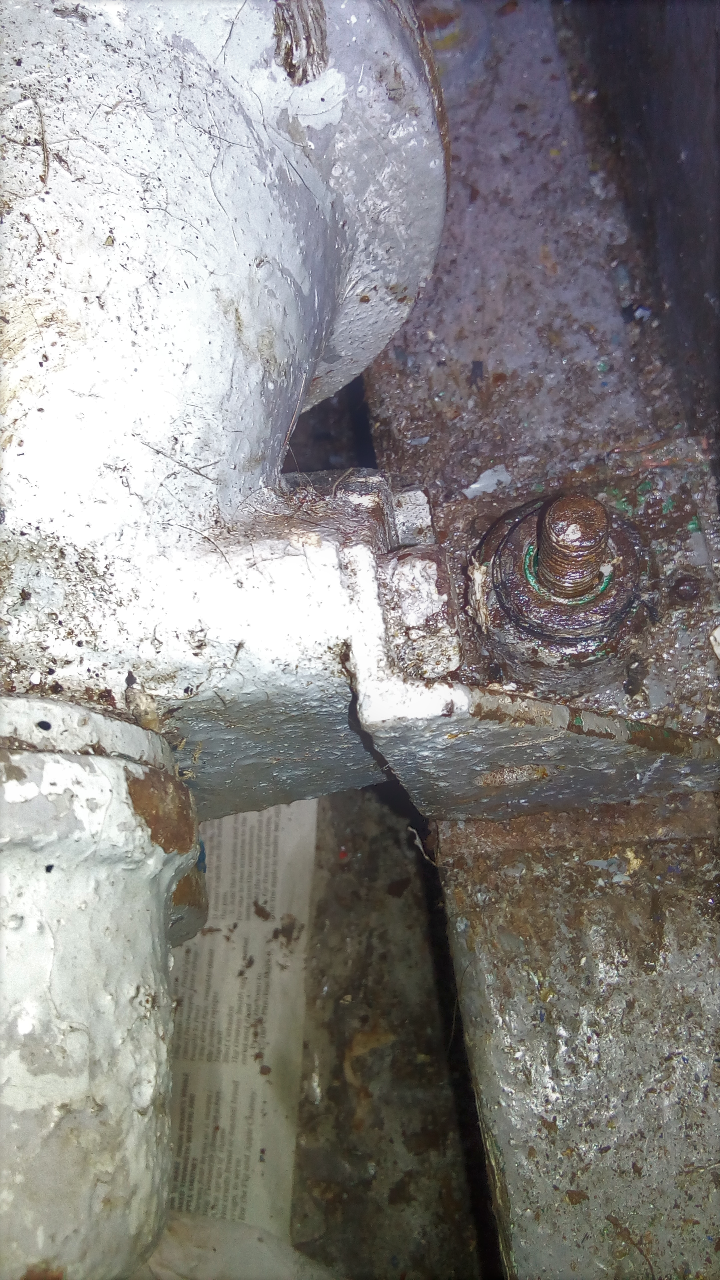
Hi Tony thanks for the drawing, do you think the drawing is actually the way the mounting is designed as it obviously impacts upon the best way of attending to the problem. The bearer is timber without any steel tapping plate or top. Your red arrow is highlighting the edge of a form of sole boarding that is attached to the side of the bearer to act as a support for the battery box that is standing on the sole as can just be seen on the left hand side. Your yellow arrow is the outer shell of the bush and not the rubber insert. the rubber insert is just below the level of the core & outer shell & looks to be OK. I am hoping that I can get the core to free off from the through bolt with enough thought. The area is not heavily corroded although it may look it as I can see the top or the core tube is clean, the trouble is that it does have a moderate length of bolt that it can seize up on. John
-
Thanks all, all ideas much appreciated. The bracket rests directly on the timber bearer, there is not enough clearance between the base of the metalistic bush and bracket to saw it off and although heat would help, the area is bounded by timber and fuel lines so a bit of a risky last resort. Now I understand how the bearer is designed that helps enormously. Thanks again.
-
Thanks...I will give it another go as at the moment I cannot get the engine off the hold down bolt bush core and cannot get the bolt out of the wood. Could try heat but I bit too risky in close proximity to timber hull structure.
-
Coincidentally I did try phosphoric acid a day or so ago but probably was too impatient because I was uncertain as to which part had siezed. I will try again, make a sealed bath around the bolt. Thanks, just confirms that it is a good idea worth trying again.
-
Thanks both, I had thought that ultimately it would be easier to solid mount the rear end but could not fully understand how the mounting had been designed as the area is a bit cluttered and over painted. Lifting the engine is the problem at the moment because the holding down bolt is, I think, well screwed into the timber bearer but also siezed in the bush core so cannot separate the two. However. Now I know which bits should separate I can work more selectively Thanks again.
-
Thanks Richard, I am assuming that the large stud in the middle is a coachscrew with a threaded end passing right through the bush and screwed into the timber bearer, so the core of the metalistic bush is temporarily siezed onto the shank of the main holding bolt or coachscrew. In that case the shims have to be fitted under the metalistic bush plate which is secured to the base of the engine bracket. That seems to have made things clearer. Now all I have to do is somehow break the sieze between the holding down stud and the core of the bush. Thanks.
-
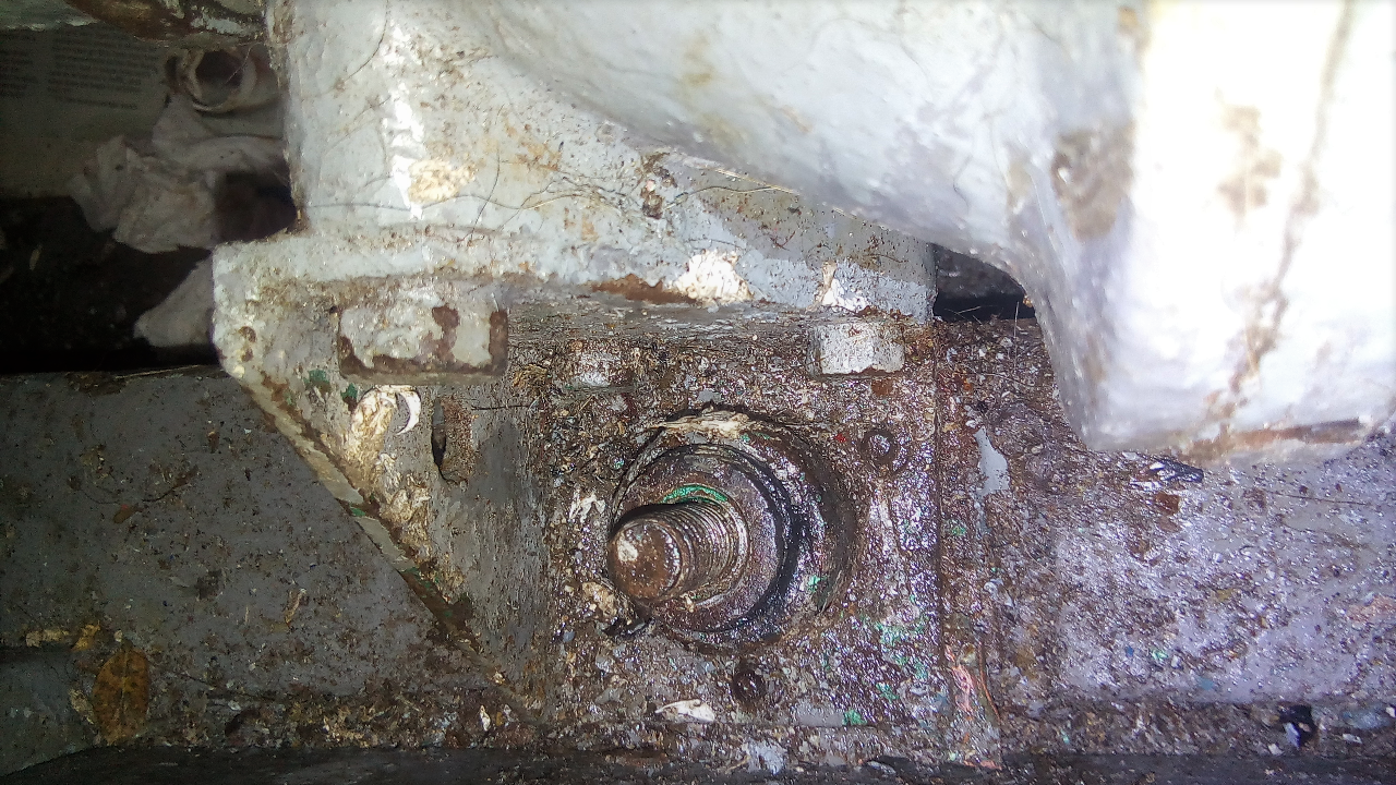
Someone might know: I have to raise the rear of the engine for shaft line up as it has dropped about 5mm. Engine is BMC Commander 2.2. The rear engine mountings are right angle brackets bolted to the bell housing. These lay on the timber bearer. There is a stud protruding with a nut on. The nut has been removed. The protruding stud seems to pass through some form of metalastic bush. There are shims beneath the base of the bracket on top of the bearer. All OK so far. I am unable to raise the engine as it seems that the protruding stud is seized in the matalastic bush. There are also three small 1/4" studs with nuts located around the base of the bracket circling the centre main stud. It would be extremely difficult to remove the bracket at this time to investigate how it is made, does anyone know the purpose of the three small studs surrounding the centre bolt & am I correct in thinking the centre stud p[asses right through the mounting & the engine should just lift off the stud & allowing more shims to be placed under the bracket. It does seem there are two bases to the bracket but full access is a bit difficult to confirm. The photos show various views but really good access is limited. It is the original design mounting & has not been altered, just cannot work out the design to enable me to focus on freeing the correct part.
-
Hi Tony that is a good idea, prefer to find the right seal, but if all else fails....Thanks
-
Ah, yes, meant to ask if anyone knew of a location that might have the seal. Can get the gearbox off without too much trouble although it is quite heavy.Thanks for the suggestions. Have checked the sizes a while ago when the box was last off but all available common imperial sizes did not match. Have not tried Primrose Engineering, will do as soon as I have the seal in my hand.
-
Engine BMC 2.2 coupled to Newage manual FNR gearbox. the front seal in the gearbox is leaking. This is the seal that is fitted in the intermediate plate between the engine and gearbox. The plate is the front cover for the gearbox and retains the gearbox oil. Standard design oil seal but obviously a specific size so most likely imperial. John
-
I have finally managed to sort most things. The old seal was definitely completely failed in that it had hardened excessively. The correct seal is completely unavailable however, just by luck I managed to remove the remnants of the oil seal within the oil seal shell and I found the metric oil seal that was a precise fit within the shell. Obviously, the shell being absolutely to correct size was no difficulty to refit. The new oil seal was just sealed into the old shell. The seal lip is slightly smaller in diameter but flexes over the shaft without too much difficulty and I think it will be fine. I have made a pair of new circumference gaskets for the plate however, these are approximately 7 or 8 thou thicker than the originals. The new ones will squeezed but by obviously not that much and I am trying to work out whether this extra thickness will hold the bearing as seen in the plate too far off causing a degree of flexing in the cast iron face plate when the assembly is bolted tight on the locking nut for the centre shaft that holds the spur gear , bearing and the oil pump cam collar in position. Any thoughts? It seems unusual that the plate outer circumference machining should have any absolutely precise relationship to the centre bearing loading. The bearing does not appear to be floating within the plate (see photographs) and I will not know until I offer the assembly up. Thank you for all your help and, if you see something you think I have missed by all means let me know. John
-
Hi Richard Glad to tell you that the oil pump drive collar is just a tight sliding fit with a small woodruff key. Once that is pulled off without too much difficulty, the plate can then be pulled off using the threaded drillings close to the bearing housing, this comes off quite easily and is not an interference fit but does need a drawer as you cannot risk prising the plate off around its perimeter for fear of fracturing it, The oil seal is fitted on the front side of the plate in a bored recess and is easily removed. Conventional oil seal although non standard size. The seal has hardened and has no chance of being efficient and needs replacement. The question is where can I get an oil seal. I assume it is English inch measures not metric, mainly because of the age. The housing (external) dia is approx 2.935, internal not checked accurately yet, but the external dia does not match any common size available.does anyone know where I can get one. Also the face gasket, big circular flange, although I could easily make this. Thanks for all input so far. John
-
Hi Richard does that mean you think the plate draws off the bearing leaving that behind, my first thought was that the cam was a separate unit sliding onto the bearing support shaft with the bearing pulling off afterwards. I think I might have seen a keyway for the cam collar, but not sure. Have not tried other than hand pulling to try to ease the cam collar off yet. It could be that it is just a tight slide fit similar to a crankshaft timing sprocket & not need specific extra work. It will be easy....when I know how it is designed, but cannot find a breakdown of the assemble to confirm. Thus the need for other member's memories,,,,if they still have them.... The question that might remain is , is there a shoulder on the plate to locate the bearing on the opposite side as there does not seem to be one this side, That would prevent the plate pulling off the bearing & leaving that behind & would not want to try to pull if this was the case. Thanks again John
-
Hi All ref oil leak on BMC gearbox After all this time, I have managed to get the gear box off with the exception of the front plate which is still in position on the bell housing. The main difference of between the smaller gear box in the photograph and my own gear box is that there is an oil pump fitted bolted to the front plate. I have removed the oil pump to make access easier. At the moment it looks as if I will need a drawer to remove the front plate and front bearing. The gear driving the epicylcic set has been removed. At this moment I am uncertain how the oil pump cam collar is fitted and whether this pulls off along with the bearing and plate assembly without any further stripping. Until I see the design I cannot be absolutely certain and I cannot see the design until it is off. There are a couple of drilled and tapped holes close to the bearing which I am assuming are in order to fit a drawer. These holes tapped 5/16 unf. Do you know of any reason why now that the front nut and locking, had been removed from the presumably bolted flywheel spigot, the assembly cannot be removed. The front plate cannot be levered off as it will fracture & not sure how tight the bearing & collar are fitted to the flywheel output shaft. The studs sticking out are If just to confirm they are tapped holes & they are not part of the assembly
-
The unit is fitted with a brass cylinder pump with change over valve for engine or gearbox drain & I have noted the adjuster on the base of the g/box. I will keep my fingers crossed that the box can be moved far enough aft to clear out without having to remove the rudder. The engine is fitted in a timber built Hillyard sailing vessel as can be seen on my website www.seasurveys.co.uk. The main difference I can see between my g/box & the smaller Captain gearbox is the circumference bolts on the flange are pocketed slightly causing the need for thin walled socket. Many thanks for your experienced help. Regards John
-
Thanks so much to both of you for the mine of information you have shared with me. I am very grateful. There are distinct similarities between the BMC Commander gearbox that I have and the photograph above in, that the gear selector splined shaft is in the identical position as is the brake band adjustment. It may be that my gearbox is slightly longer but it is difficult to tell from the photographs. I will look for the plate as Tony suggests, I can see now why it would not be possible to remove the gear box still attached to the bell housing. Presumably the oil seal is fitted in the sandwiched face plate running on the plain section of shaft directly forward of the spur gear aft of the flywheel bolts. In this case, I can see that it is obvious as soon as the bolts have been released from the gear box the oil will be lost so it needs to be drained out prior to stripping. All that I have to sort out now is to figure some way of removing one or two of the flange bolts as, it does appear that some stage in the past they have been replaced with standard head bolts instead of the extended head bolts. I am sure this can be overcome with some ground sockets as previously suggested. Tony's suggestion about installing long dowels to be able to to remove the gear box and keep it supported is a good idea. In this particular case the engine support rear is on the bell housing and it does not incorporate an engine bearer plate as shows in Richard's photograph. When I go down next then I will confirm the way it has been suggested that it is designed. Just never noticed that there was an additional plate between the gearbox flange & bell housing. If I have any further questions over the external design that have not been answered would you mind me just putting them to you? Once the gearbox is off then I will be able to sort it without too much difficulty, it is just not knowing the transmission method to the gearbox which has now been comprehensively explained. I have spoken to some experienced marine engineers who claimed to have had experience of these units who absolutely assured me that the bell housing can be removed bringing the gearbox with it. I just had doubts over what they were saying. Thanks again. John www.seasurveys.co.uk
-
Thanks Tony I'll probably remove the reduction gear separately to minimize weight & awkwardness & from what I understand you are saying,, remove the gearbox from the bell housing without interfering with the bell housing & hope the drive separates easily on a spline or similar. Once the gearbox is clear then normal disassembly as required to access the oil seal. It is the intermediate plate that is the unknown quantity at the moment & how that prevents or restricts removal. I'll try to find some exploded view somewhere but no luck at the moment. Thanks again. John