Brian422
-
Posts
134 -
Joined
-
Last visited
Content Type
Profiles
Forums
Events
Gallery
Blogs
Store
Everything posted by Brian422
-
Travel power - doesn’t work, can anyone help?
Brian422 replied to kingbillymatt's topic in Boat Building & Maintenance
I Have a Travel Power and Victron Multiplus. with three way switch; inputs from Travel Power and Shoreline, output to Multiplus. Switch to Select Input from Travel Power the Multplus Mains Input LED is on. -
One Forum contributor reduced alternator pulley size so that it would produce output at lower engine speed.
-
Be careful when buying ebay £50 diagnostic Kit. I purchased a kit only to find out they're only suitable for Webasto with digital control board. My Webasto was installed in 2009 and has analogue control board board. Hopefully, if your Webasto is relatively new you shouldn't have a problem. Regards Brian.

-
Hope this helps: https://www.butlertechnik.com/downloads/Webasto_Heater_Marine_Thermo_Top_installation_manual.pdf Page 11
-
Do I have to replace all 3 of my leisure batteries
Brian422 replied to Wiggywormcake's topic in General Boating
I'm assuming alternator output is good when engine running. When I were but a lad I had an original mini that, if used every day was fine but left longer would flatten the battery. Output from alternator appeared normal. One day out of desperation I decided to remove the alternators positive feed. Battery remained charged. Diagnosed as faulty Diode Pack. Worth measuring battery voltage and removing alternator positive lead at night and measuring voltage in morning? -
I get the if it's working leave alone. My query was more about understanding what are the differences between the two pumps?
-
Thanks for reply but I'd found listing on butlertecnik. Really want to know whether there's a requirement to replace a little used DP2 with a DP30.2.
-
From new my Diesel Webasto Thermo Top C has used, according to it's profile, a DP2 Dosing Pump. I understand a Diesel installation should use Dosing Pump DP 30.2. I would be grateful if someone would advise on the differences between the two pumps and should I replace the DP2. Regards and Thanks Brian.
-
Purchased kit before attempting Webasto repair but only required Webasto Trouble Shooting Guide. Purchased Ross Tech Full VCDS shortly after buying VW saloon because as we all know modern vehicles are complex, unlike Webasto Water Heaters, and without diagnostics it's impossible even to diagnose any problems. I use VCDS regularly just to keep an eye out for any potential problems. Thinking o purchasing OBDEleven for convenience. If I was servicing Webastos regularly then I would purchase 'proper' Webasto diagnostic kit but as it might not be used more than once or twice a year .... .
-
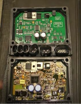
Top PCB is Analogue, Bottom W-Bus. Connections mentioned in Workshop Manual are for analogue only:
-
I've attempted multiple new installs without success. Having requested details to enable items return have been contacted by seller and given step by step instructions. I'm not convinced as software is more focused on W-Bus protocol; my Thermo Top C is the Analogue version. However, will follow instructions and report back on results.
-
Update: Managed to remove Combustion Fan Motor from housing without damaging Fan. Quite a lot of oil on gasket and between gasket and housing; bolts securing motor to housing were loose. Shaft rotation notchy - possibly commutator or damaged bearing; source of oil. Still no joy in getting W.T.T. to communicate with Webasto; haven't given up yet!
-
Calling all you computer experts with experience of W.T.T. Adaptor https://www.ebay.co.uk/itm/402121622145. Boat has Webasto Thermo Top C (Not W-Bus) with temperature control via Honeywell Room Thermostat and Motorised Valve. Purchased W.T.T. Adaptor and software to enable Windows 10 Laptop to monitor Thermo Top C but unfortunately unable to open communications with W.T.T. Adaptor Windows10 Laptop W.T.T.version 2.16.1 (latest available) and selected appropriate model from Menu. Have loaded latest W.T.T. Drivers. Device Manager Com Port same as in W.T.T in Extras but any attempts to Start Diagnosis results in 'selected com port can not be used' message irrespective of selected port; automatic port selection results in endless repeat of same message and having to power down laptop to terminate. Have been playing email tennis with supplier without success. Grateful for any help or guidance. Regards Brian
-
Diagnostic kit took 6 weeks to arrive but given the distance and current postal strikes quite understandable. Haven't yet used because away from boat and Webasto is current sitting on bench. Dismantled Combustion Fan housing, found motor seized and what looks like oil residue, not diesel, possibly from fan bearings inside housing. Have purchased replacement. Just hoping that motor didn't draw excess current and damage electronics. Unfortunately removing motor for further examination would mean damaging fan. Perhaps will when curiosity gets the better of me. Regards Brian.
-
However, you're in charge. If you don't want help and you feel your being rushed, thank them for their offer and politely suggest they go away!
-
Hi Chevron. Thank you for your advice and guidance. Will order kit with additional leads. Regards Brian
-
Hi Opener. The short answer to your qustion is yes. Pressing the timer override illuminates the Timer display, then just it's listen and wait. Unfortunately there's no flashing lights indicating fault code.
-
Thanks for your suggestions and thoughts. I don't have a dedicated power switch just a Timer with manual override for instant operation. Interested in vag-com suggestion as have RossTec; will investigate. Regards Brian.
-
I suspect the Combustion Air Fan is faulty; no turbine whine on start, Water Pump working, but I'd like to make sure before going any further. Unfortunately the cost of Webasto diagnostic device is really expensive. I'd be grateful for any feedback from users of device linked below:- https://www.ebay.co.uk/itm/402121622145 Regards and Thanks Brian.
-
Apologies for late response. As a temporary measure as I have a battery charger and in marina, I've decided to go with Tonys' suggestion. Regards and thanks to all Brian.
-
Current configuration 3x 10⁵ Ah Domestic Batteries, 105 Ah Starter Battery and 105 Ah Bow Thruster Battery - no pun intended. Domestic Batteries maintained by Victron Multiplus but Starter and Bow Thruster Batteries are charged by dedicated Alternator via Split Charge Diode when engine running. Thinking of fitting Voltage Sensitive Relay but until then, would disconnecting Alternator cable that feeds centre of Split Charge Diode and connecting it to Domestic Batteries supply during winter layup be practical. Also advise on VSR appreciated. Regards Brian.
-
I'm looking to purchase a single U channel section Brass Hatch Cover Runner with external dimensions 10 mm x approximately 2 m as a split in one opened during cover refitting and would be grateful for contact details of supplier. Regards and Thanks Brian.
-
It is said that the learning curve is steep. Getting on the bottom is difficult enough however I know more about Split Charge Diode Isolation and the layout of my boats' electrics. Also have removing alternator down to a fine art 😉. Happy to report Starter Alternator Regulator replaced; B Terminal 13.88 volts engine running, 0 volts engine stopped. Thank you all for your help and guidance. Regards Brian.
-
Boat has electric Bow Thruster and Sterling Split Charge Diode Isolator so being puzzled decided to dig a little deeper. Three posts on isolator, the middle being mark with red paint whilst the remaing posts are offset. Measured voltages before disconnecting to check diodes (Engine Stopped). Middle post (red paint) 2.91 volts and connected to Starter Alternator. Left Hand post 12.63 volts connected to Starter Battery. Right Hand post 11.82 volts connected to Bow Thruster Battery. There's also a 15 amp fuse connected between middle post and right hand post; suspect feed to Bow Thruster Control Panel. Individual diodes pass DMV diode check; approx 460 Ohms in forward direction and infinite in reverse with no leakage to case. From what I can gather fromYou Tube, Middle Post with red paint should go to Starter Battery with Sarter Alternator and Bow Thruster Battery supply connected seperately to either of the remaining post. This would appear incorrect, however, when engine running Starter Alternator should provide voltage supply from middle post via forwad biased diodes to both Starter and Bow Thruster Batteries. This configuration would explain why voltage on Starter Alternator B Terminal appears low. These connections are as made when boat was built! All suggestions gratefully recieved apart from need for 'Girlie Button'.
-
My meter is a DVM with very high input restance so will have no effect on voltage. 12.63 volt on end of disconnected cable; agreed there's no DVM will draw enough current. An open connection would give no voltage at cable end.